Peugeot 207 1.4 16v 2006 cambelt change instructions and replacement inteval. Full guide!
Special tools
- Exhaust camshaft sprocket timing pin – No.(-).0132-AJ1.
- Flywheel locking tool – No.(-)0132-QY.
- Inlet camshaft sprocket timing pin – No.(-).0194-A.
- Timing belt retaining clip – No.(-).0132-AK.
- 3 mm drill bit.
Special precautions
- Disconnect battery earth lead.
- DO NOT turn crankshaft or camshaft when timing belt removed.
- Remove spark plugs to ease turning engine.
- Turn engine in normal direction of rotation (unless otherwise stated).
- DO NOT turn engine via camshaft or other sprockets.
- Observe all tightening torques.
Repair times – hrs
| Camshaft drive belt/chain – R & I | 1,70 |
Valve timing procedures
Removal
- Raise and support front of vehicle.
- Remove:
- RH front wheel.
- RH splash guard.
- Auxiliary drive belt.
- Crankshaft pulley bolts [1] .
- Crankshaft pulley [2] .
- Engine top cover.
- Support engine.
- Remove:
- RH engine mounting.
- RH engine mounting bracket.
- Timing belt upper cover [3] .
- Timing belt lower cover [4] .
- Turn crankshaft clockwise to TDC on No.1 cylinder.
- Remove oil filter (if necessary).
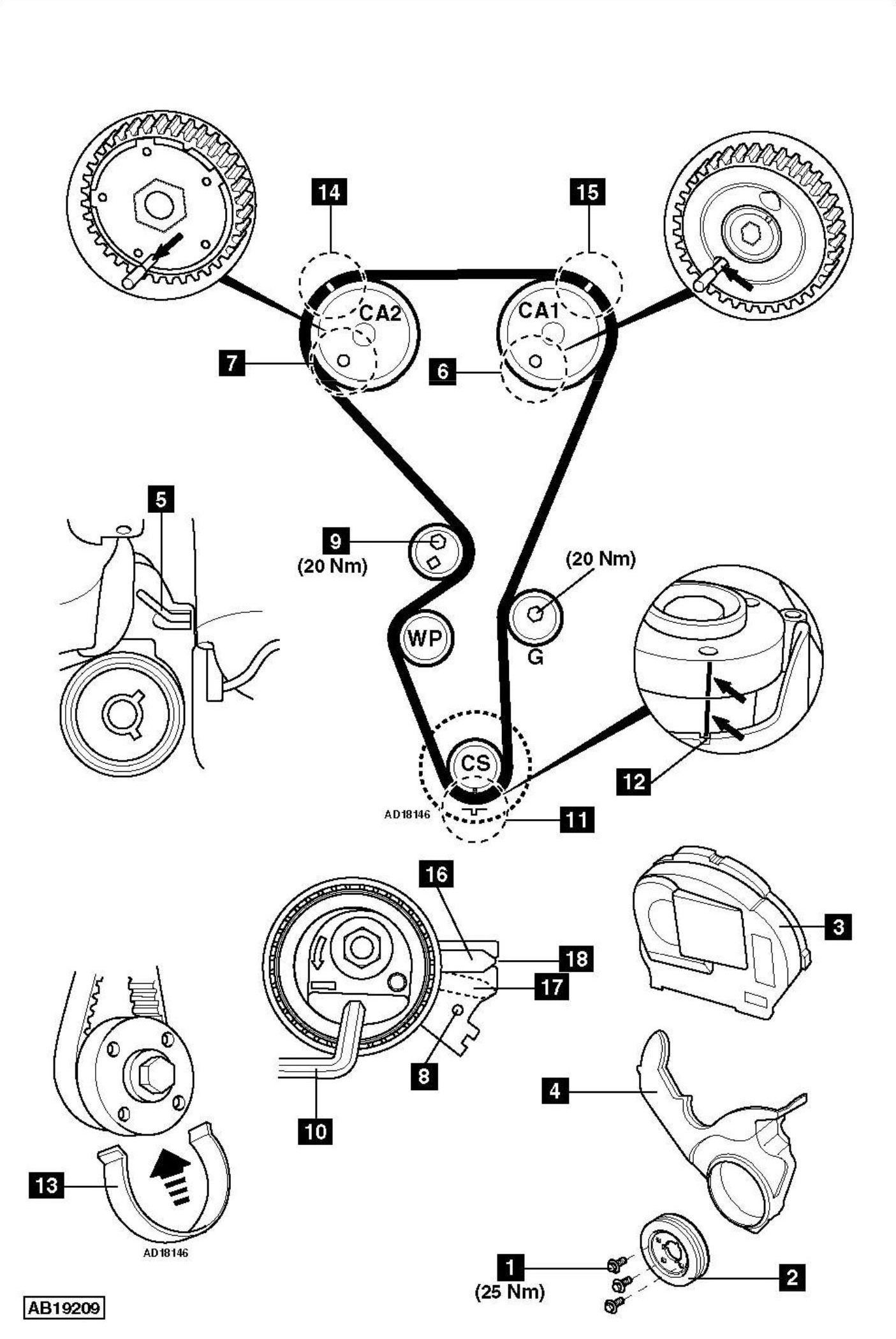
- Fit flywheel locking tool [5] . Tool No.(-)0132-QY.
- Insert exhaust camshaft sprocket timing pin [6] . Tool No.(-).0132-AJ1.
- Insert inlet camshaft sprocket timing pin [7] . Tool No.(-).0194-A.
- Insert 3 mm drill bit into tensioner backplate [8] .
- Slacken tensioner pulley nut to release tension on belt [9] .
- Turn tensioner pulley clockwise away from belt. Use Allen key [10] . Lightly tighten nut [9] .
NOTE: DO NOT turn tensioner pulley 360°. - Remove timing belt.
NOTE: DO NOT refit used belt.
Installation
NOTE: Tensioner pulley and guide pulley must be replaced.
- Check water pump sprocket for smooth operation.
- Ensure timing pins located correctly [6] & [7] .
- Ensure flywheel locking tool located correctly [5] .
- Fit new tensioner pulley. Finger tighten nut [9] .
- Insert 3 mm drill bit into tensioner backplate [8] .
- Turn tensioner pulley clockwise. Use Allen key [10] . Lightly tighten nut [9] .
NOTE: DO NOT turn tensioner pulley 360°. - Fit new guide pulley. Tighten bolt. Tightening torque: 20 Nm.
- Fit timing belt to crankshaft sprocket.
- Ensure mark on belt aligned with mark on crankshaft sprocket [11] . Ensure marks aligned with notch [12] .
- Secure belt to crankshaft sprocket with retaining clip. Tool No.(-).0132-AK [13] .
- Fit timing belt to remaining sprockets and pulleys.
- Ensure marks on belt at positions shown [14] & [15] .
- Remove:
- 3 mm drill bit [8] .
- Retaining clip [13] .
- Slacken tensioner pulley nut [9] .
- Turn tensioner pulley anti-clockwise until pointer [16] at position shown [17] . Use Allen key [10] .
- NOTE: Tensioner pulley pointer [16] must not pass backplate hole [8] .
- ighten tensioner pulley nut [9] . Tightening torque: 20 Nm.
- Remove:
- Timing pins [6] & [7] .
- Locking tool [5] .
- Turn crankshaft four turns clockwise to TDC on No.1 cylinder.
NOTE: DO NOT allow crankshaft to turn anti-clockwise. - Fit flywheel locking tool [5] .
- Hold tensioner pulley. Use Allen key [10] . Slacken tensioner pulley nut [9] .
- Turn tensioner pulley clockwise until pointer [16] at position shown [18] . Use Allen key [10] .
- Hold tensioner pulley. Use Allen key [10] . Tighten tensioner pulley nut [9] . Tightening torque: 20 Nm.
NOTE: Ensure tensioner pulley does not move when tightening nut [9] . If tensioner pulley moves: Repeat tensioning procedure. - Remove locking tool [5] .
- Turn crankshaft two turns clockwise.
- Ensure tensioner pulley pointer [16] aligned with notch or 2 mm maximum to the left or right of notch [18] . If not, repeat tensioning procedure.
- Ensure timing pins can be inserted easily [6] & [7] . If not, repeat installation procedure.
- Ensure locking tool can be inserted easily [5] . If not, repeat installation procedure.
- Remove:
- Timing pins [6] & [7] .
- Locking tool [5] .
- Install components in reverse order of removal.
- Tighten crankshaft pulley bolts [1] . Tightening torque: 25 Nm.