Citroen Jumper 2.2HDi 2003 cambelt change instructions and replacement inteval. Full guide!
Special tools
- Flywheel locking tool – Citroen No.(-).188.F.
- Flywheel timing pin – Citroen No.(-).0188.Y.
- Camshaft timing pin – Citroen No.(-).0188.M.
- Tensioning tool – Citroen No.(-).0188.J2.
- Timing belt retaining clip – Citroen No.(-).0188.K.
- Tension gauge – SEEM CTG 105.5M.
- Crankshaft pulley puller – Citroen No.(-).0188.P.
Special precautions
- Disconnect battery earth lead.
- DO NOT turn crankshaft or camshaft when timing belt removed.
- Remove spark plugs to ease turning engine.
- Turn engine in normal direction of rotation (unless otherwise stated).
- DO NOT turn engine via camshaft or other sprockets.
- Observe all tightening torques.
Repair times – hrs
| Camshaft drive belt/chain – C & A | 3,00 |
| Camshaft drive belt/chain, AC – C & A | 3,30 |
| Camshaft drive belt/chain – R & I | 3,70 |
| Camshaft drive belt/chain, AC – R & I | 4,00 |
Valve timing procedures
Removal
NOTE: The high-pressure fuel pump fitted to this engine does not require timing.
- Raise and support front of vehicle.
- Remove:
- Engine lower cover.
- RH front wheel.
- RH splash guard.
- Auxiliary drive belt.
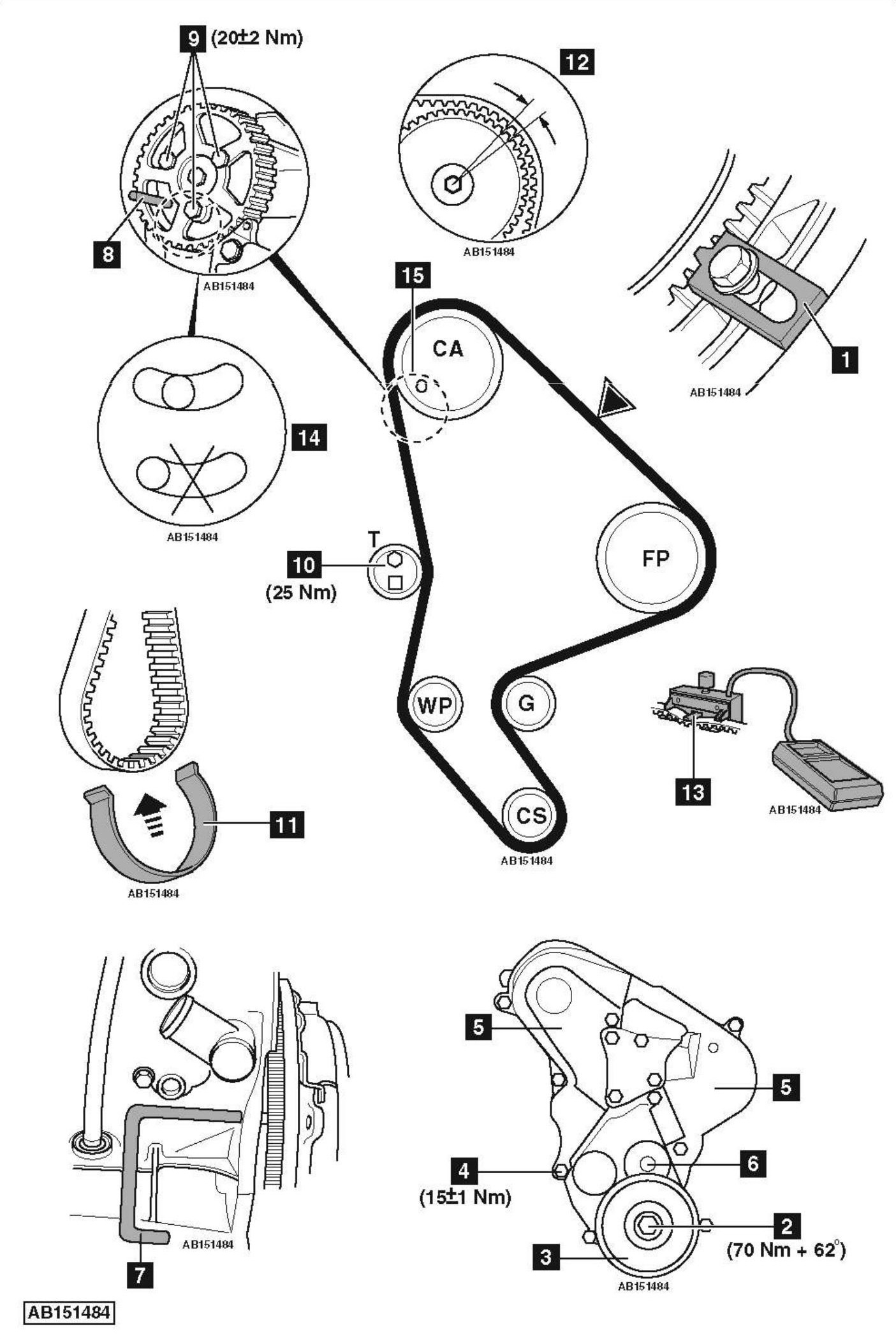
- Lock flywheel [1] . Use tool No.(-).188.F.
- Remove crankshaft pulley bolt [2] .
- Refit crankshaft pulley bolt without thrust washer [2] .
- Fit crankshaft pulley puller. Tool No.(-).0188.P.
- Detach crankshaft pulley from crankshaft.
- Remove:
- Crankshaft pulley puller.
- Crankshaft pulley bolt [2] .
- Crankshaft pulley [3] .
- Flywheel locking tool [1] .
- Support engine.
- Remove:
- EGR pipe heat shield.
- EGR pipe.
- RH engine mounting and bracket.
- Bolt [4] .
- Timing belt upper covers [5] .
- Timing belt lower cover [6] .
- Refit bolt fitted with a 17 mm thick spacer [4] . Tighten bolt to 15±1 Nm.
- Turn crankshaft clockwise to setting position.
- Insert timing pin in flywheel [7] . Tool No.(-).0188.Y.
- Insert timing pin in camshaft sprocket [8] . Tool No.(-).0188.M.
- Slacken camshaft sprocket bolts [9] .
- Slacken tensioner pulley bolt [10] .
- Turn tensioner pulley clockwise away from belt. Use tool No.(-).0188.J2.
- Remove timing belt.
Installation
- Check tensioner pulley, guide pulley and water pump sprocket for smooth operation.
- Ensure timing pins located correctly [7] & [8] .
- Tighten bolts finger tight [9] .
- Turn camshaft sprocket fully clockwise in slotted holes.
- Fit timing belt to crankshaft sprocket.
- Secure belt to crankshaft sprocket with retaining clip [11] . Use tool No.(-).0188.K.
- Fit timing belt in anti-clockwise direction. Ensure belt is taut between sprockets.
- Lay belt on camshaft sprocket teeth. Engage belt teeth by turning sprocket slightly anti-clockwise.
NOTE: Angular movement of sprocket must not be more than one tooth space [12] . - Fit timing belt to water pump sprocket and tensioner pulley.
- Remove retaining clip [11] .
- Attach tension gauge to belt at [13] . Tool No.SEEM CTG 105.5M.
- Turn tensioner pulley anti-clockwise until tension gauge indicates 98±2 SEEM units.
- Tighten tensioner pulley bolt [10] . Tightening torque: 25 Nm.
- Ensure sprocket bolts not at end of slotted holes [14] .
- If necessary: Repeat installation procedure.
- Tighten camshaft sprocket bolts [9] . Tightening torque: 20 Nm.
- Remove:
- Timing pins [7] & [8] .
- Tension gauge [13] .
- Turn crankshaft eight turns clockwise to setting position.
- Insert timing pin [7] .
- Slacken camshaft sprocket bolts [9] .
- Insert timing pin [8] .
- Slacken tensioner pulley bolt to release tension on belt [10] .
- Attach tension gauge to belt at [13] .
- Turn tensioner pulley anti-clockwise until tension gauge indicates 54±2 SEEM units.
- Tighten tensioner pulley bolt [10] . Tightening torque: 25 Nm.
- Tighten camshaft sprocket bolts [9] . Tightening torque: 20±2 Nm.
- Remove tension gauge [13] .
- Check belt tension: Attach tension gauge to belt at [13] . Tension gauge should indicate 54±3 SEEM units.
- If not: Repeat tensioning procedure.
- Remove:
- Tension gauge [13] .
- Timing pins [7] & [8] .
- Turn crankshaft two turns clockwise to setting position.
- Insert timing pin in flywheel [7] .
- Ensure timing pin can be inserted easily [8] .
- If locking tool cannot be inserted: Visually check camshaft sprocket hole [15] aligned with hole in cylinder head. If holes are misaligned, this should be less than 1 mm. If misalignment of holes more than 1 mm, repeat installation procedure.
- Remove timing pins [7] & [8] .
- Remove bolt and 17 mm spacer [4] .
- Fit:
- Timing belt upper covers [5] .
- Timing belt lower cover [6] .
- Bolt [4] . Tighten bolt to 15±1 Nm.
- Flywheel locking tool [1] .
- Remove crankshaft pulley bolt [2] .
- Refit crankshaft pulley [3] .
- Coat crankshaft pulley bolt with suitable thread locking compound.
- Tighten crankshaft pulley bolt [2] . Tightening torque: 70 Nm + 62°.
- Remove flywheel locking tool [1] .
- Install components in reverse order of removal.