Volkswagen Golf VII 2.0TDi 2013 cambelt change instructions and replacement inteval. Full guide!
Special tools
- Auxiliary drive belt tensioner locking pin – No.T10060A.
- Camshaft locking tool – No.3359.
- Camshaft sprocket holding tool – No.T10172/11.
- Crankshaft sprocket locking tool – No.T10490.
- High-pressure fuel pump locking tool – No.T10492.
- High-pressure fuel pump sprocket holding tool – No.T10051.
- Tensioner pulley adjusting tool – No.T10264.
- Tensioner pulley locking tool – No.T10265.
- Tool set – No.T10395.
Special precautions
- Disconnect battery earth lead.
- DO NOT turn crankshaft or camshaft when timing belt removed.
- Remove spark plugs to ease turning engine.
- Turn engine in normal direction of rotation (unless otherwise stated).
- DO NOT turn engine via camshaft or other sprockets.
- Observe all tightening torques.
Valve timing procedures
Removal
- Raise and support front of vehicle.
- Remove:
- Engine upper cover.
- Engine undershield.
- RH front wheel.
- RH splash guard.
- Disconnect:
- Coolant level sensor multi-plug.
- Fuel hose support brackets.
- Coolant expansion tank top hose.
- Move coolant expansion tank to one side. DO NOT disconnect hoses.
- Reposition fuel filter. DO NOT disconnect fuel pipes.
- Support engine.
- Remove RH engine mounting and bracket.
- Disconnect:
- Fuel supply and return pipes.
- Diesel particulate filter (DPF) pressure sensor multi-plug.
- Diesel particulate filter (DPF) pressure pipe from timing belt upper cover.
- Remove:
- Exhaust gas temperature sensor. Use tool from tool set No.T10395.
- Diesel particulate filter (DPF) pressure sensor bracket.
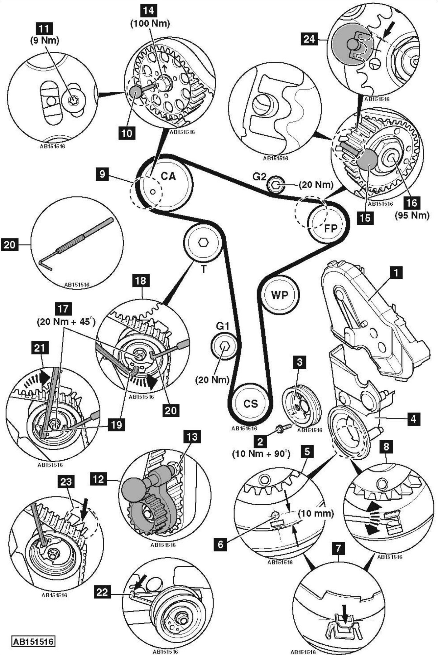
- Timing belt upper cover [1] .
- Auxiliary drive belt. Use tool No.T10060A.
NOTE: Mark direction of rotation on belt with chalk if belt is to be reused.
- Crankshaft pulley bolts [2] .
- Crankshaft pulley [3] .
- Remove timing belt lower cover [4] .NOTE: There are two types of timing belt lower cover [4] . When removing timing belt lower cover, locking tab may need to be removed.
- Timing belt lower cover early type [5] :
- Mark timing belt cover at position shown [6] . Distance between mark and inner edge of timing belt cover is 10 mm.
- Drill an 8 mm diameter hole into timing belt cover [6] .
- Insert screwdriver through hole and remove locking tab [7] .
- Timing belt lower cover later type [8] :
- Insert screwdriver through hole and remove locking tab [7] .
- Turn crankshaft slowly clockwise until camshaft sprocket timing hole at 8 o’clock position [9] .
- Lock camshaft [10] . Use tool No.3359.
- Slacken camshaft sprocket bolt 1/2 turn [11] .
- Lock crankshaft sprocket [12] . Use tool No.T10490.
NOTE: Engine at TDC on No.1 cylinder. - Ensure lug of crankshaft sprocket locking tool located in oil seal housing [13] .
- Remove camshaft locking tool [10] .
- Hold camshaft sprocket. Use tool No.T10172/11.
- Slacken camshaft sprocket centre bolt [14] .
- Lock camshaft [10] .
- Lock high-pressure fuel pump [15] . Use tool No.T10492.
- Remove high-pressure fuel pump locking tool [15] .
- Hold high-pressure fuel pump sprocket. Use tool No.T10051.
- Slacken high-pressure fuel pump sprocket nut 1/4 turn [16] .
- Lock high-pressure fuel pump [15] .
- Slacken tensioner pulley nut [17] .
- Turn tensioner pulley anti-clockwise until locking tool can be inserted [18] . Use tool No.T10264 [19] .
- Insert locking tool in tensioner pulley [20] . Tool No.T10265.
- Turn tensioner pulley fully clockwise until it reaches stop [21] . Use tool No.T10264 [19] .
- Tighten tensioner pulley nut finger tight [17] .
- Remove timing belt, starting at water pump.
Installation
NOTE: Engine must be COLD.
- Remove tensioner pulley nut [17] .
- Fit new tensioner pulley nut [17] . Tighten nut finger tight.
- Ensure tensioner pulley locking tool inserted [20] .
- Ensure tensioner pulley against stop [21] .
- Ensure tensioner pulley retaining lug is properly engaged [22] .
- Ensure crankshaft sprocket locking tool located correctly [12] .
- Ensure camshaft locked with tool [10] .
- Ensure high-pressure fuel pump locked with tool [15] .
NOTE: Sprockets should turn freely but not tilt. - Turn camshaft sprocket fully clockwise.
- Turn high-pressure fuel pump sprocket fully clockwise.
- Fit timing belt in clockwise direction, starting at crankshaft sprocket.
- Slacken tensioner pulley nut [17] .
- Remove locking tool from tensioner pulley [20] .
- Ensure camshaft sprocket bolt not at end of slotted hole [11] . If not: Repeat installation procedure.
- Turn tensioner pulley slowly clockwise until pointer aligned with notch [23] . Use tool No.T10264 [19] .
NOTE: Ensure tensioner pulley nut does not turn [17] . - Hold tensioner pulley. Use tool No.T10264 [19] .
- Tighten tensioner pulley nut [17] . Tightening torque: 20 Nm + 45°.
- Turn camshaft sprocket anti-clockwise to remove slack from belt between camshaft sprocket and high-pressure fuel pump sprocket. Use tool No.T10172/11.
- Hold camshaft sprocket. Use tool No.T10172/11.
- Tighten camshaft sprocket centre bolt [14] . Tightening torque: 10 Nm.
- Tighten high-pressure fuel pump sprocket nut [16] . Tightening torque: 10 Nm.
- Ensure high-pressure fuel pump sprocket mark at position shown [24] . If not: Remove timing belt, turn high pressure fuel pump sprocket one tooth clockwise and repeat installation procedure.
- Remove:
- Camshaft locking tool [10] .
- High-pressure fuel pump locking tool [15] .
- Crankshaft sprocket locking tool [12] .
- Turn crankshaft slowly two turns clockwise until just before TDC on No.1 cylinder.
- Fit crankshaft sprocket locking tool while slowly turning crankshaft to TDC [12] .
- Ensure lug of crankshaft sprocket locking tool located in oil seal housing [13] .
- Ensure camshaft locking tool can be inserted easily [10] .
NOTE: DO NOT insert high-pressure fuel pump locking tool as alignment hole may be slightly misaligned. No adjustment required. - Ensure tensioner pulley pointer aligned with notch or 5 mm maximum to the left or right of notch [23] . If not: Repeat installation procedure.
- If camshaft locking tool cannot be inserted easily [10] :
- Remove lug of crankshaft sprocket locking tool from hole in oil seal housing.
- Turn crankshaft anti-clockwise until lug of locking tool just passes hole in oil seal housing.
- Turn crankshaft clockwise until camshaft locking tool can be inserted [10] .
- Hold camshaft sprocket. Use tool No.T10172/11.
- Slacken camshaft sprocket centre bolt [14] .
NOTE: Lug of crankshaft sprocket locking tool will be positioned to the left or right of hole in oil seal housing.
- If lug of crankshaft sprocket locking tool is positioned to the left of hole in oil seal housing:
- Turn crankshaft clockwise until lug and hole aligned [13] .
- Lock crankshaft sprocket [12] .
- Hold camshaft sprocket. Use tool No.T10172/11.
- Tighten camshaft sprocket centre bolt [14] . Tightening torque: 20 Nm.
- If lug of crankshaft sprocket locking tool is positioned to the right of hole in oil seal housing:
- Turn crankshaft anti-clockwise until lug of locking tool just passes hole in oil seal housing.
- Turn crankshaft clockwise until lug and hole aligned [13] .
- Lock crankshaft sprocket [12] .
- Hold camshaft sprocket. Use tool No.T10172/11.
- Tighten camshaft sprocket centre bolt [14] . Tightening torque: 20 Nm.
- Remove locking tools [10] & [12] .
- Turn crankshaft slowly two turns clockwise until just before TDC on No.1 cylinder.
- Fit crankshaft sprocket locking tool while slowly turning crankshaft to TDC [12] .
- Ensure lug of crankshaft sprocket locking tool located in oil seal housing [13] .
- Ensure camshaft locking tool can be inserted easily [10] .
- Remove camshaft locking tool [10] .
- Hold camshaft sprocket. Use tool No.T10172/11.
- Tighten camshaft sprocket centre bolt [14] . Tightening torque: 100 Nm.
- Hold high-pressure fuel pump sprocket. Use tool No.T10051.
- Tighten high-pressure fuel pump sprocket nut [16] . Tightening torque: 95 Nm.
- Remove crankshaft sprocket locking tool [12] .
- Turn crankshaft slowly two turns clockwise until just before TDC on No.1 cylinder.
- Fit crankshaft sprocket locking tool while slowly turning crankshaft to TDC [12] .
- Ensure lug of crankshaft sprocket locking tool located in oil seal housing [13] .
- Ensure camshaft locking tool can be inserted easily [10] .
- Remove locking tools [10] & [12] .
- Tighten camshaft sprocket bolt [11] . Tightening torque: 9 Nm.
- Install components in reverse order of removal.
NOTE: If fitting a new timing belt lower cover [4] , ensure locking tab has been removed [7] . - Tighten crankshaft pulley bolts [2] . Tightening torque: 10 Nm + 90°. Use new bolts.