Nissan NV200 1.5 DCI 2012 cambelt change instructions and replacement inteval. Full guide!
Special tools
- Crankshaft timing pin – Nissan No.KV113B0130 (No.Mot.1489).
- Camshaft timing pin – Nissan No.KV113B0110 (No.Mot.1430).
Special precautions
- Disconnect battery earth lead.
- DO NOT turn crankshaft or camshaft when timing belt removed.
- Remove glow plugs to ease turning engine.
- Turn engine in normal direction of rotation (unless otherwise stated).
- DO NOT turn engine via camshaft or other sprockets.
- Observe all tightening torques.
Valve timing procedures
Removal
NOTE: If timing belt has failed, it is possible that the camshaft sprocket key has been damaged which would cause incorrect valve timing.
- Raise and support front of vehicle.
- Remove:
- Engine undershield.
- RH front wheel.
- Note: RH headlamp.
- RH wheel arch liner.
- Engine top cover.
- NV 200/London Taxi/Evalia: Windscreen washer reservoir.
- Auxiliary drive belt. DO NOT reuse belt.
- Auxiliary drive belt tensioner.
- Support engine.
- Remove:
- RH engine tie-bar.
- RH engine mounting.
- RH engine mounting intermediate bracket.
- Note: Coolant expansion tank. DO NOT disconnect hoses.
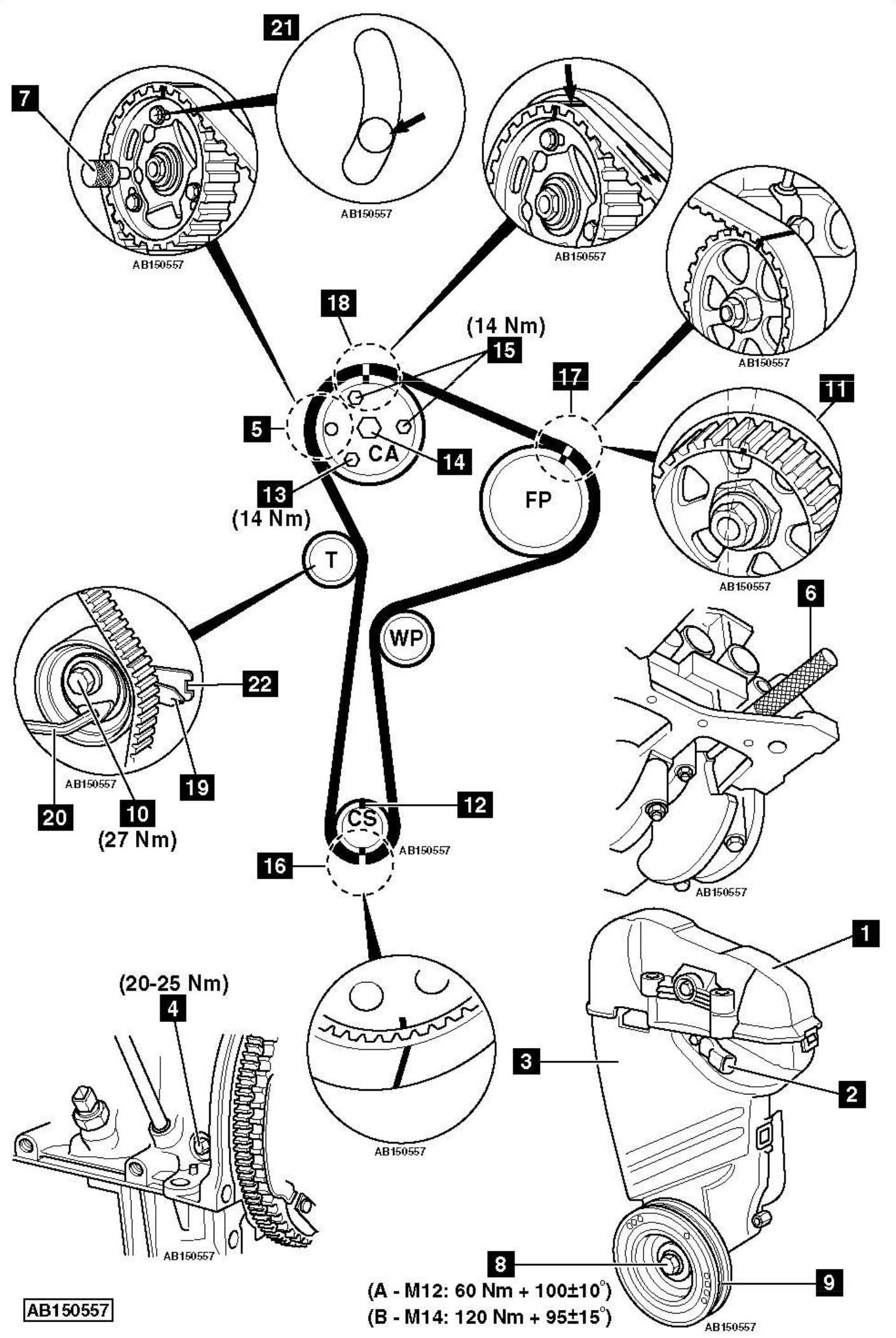
- Timing belt upper cover [1] .
- Camshaft position (CMP) sensor (if fitted) [2] .
- RH engine mounting bracket.
- Timing belt lower cover [3] .
- Blanking plug from cylinder block [4] .
- Turn crankshaft clockwise until timing pin locating hole on camshaft sprocket almost aligned with hole in cylinder head [5] .
- Insert crankshaft timing pin [6] . Tool No.KV113B0130 (No.Mot.1489).
- Turn crankshaft slightly until crankshaft web stops against timing pin [6] .
- Insert camshaft timing pin [7] . Tool No.KV113B0110 (No.Mot.1430).
- Remove:
- Timing pins [6] & [7] .
- Crankshaft position (CKP) sensor.
- Lock flywheel with large screwdriver. Slacken crankshaft pulley bolt [8] .
- Remove:
- Crankshaft pulley bolt [8] .
- Crankshaft pulley [9] .
- Slacken tensioner pulley bolt [10] . Move tensioner pulley away from belt.
- Remove:
- Timing belt.
- Tensioner pulley.
Installation
- Fit new tensioner pulley. Finger tighten bolt [10] . Ensure tensioner pulley locking tab located correctly in cylinder head.
- Remove crankshaft sprocket. Degrease sprocket. Degrease end of crankshaft.
WARNING: Failure to degrease components may lead to sprocket slipping on crankshaft, resulting in severe engine damage. - Refit crankshaft sprocket.
- Insert camshaft timing pin [7] .
- Ensure high-pressure fuel pump sprocket timing mark aligned as shown [11] .
- Ensure crankshaft sprocket keyway at 12 o’clock position [12] .
- Temporarily fit crankshaft pulley bolt with a spacer [8] .
- Insert crankshaft timing pin [6] .
- Remove one camshaft sprocket bolt [13] .
NOTE: DO NOT slacken camshaft sprocket hub nut [14] . - Slacken two camshaft sprocket bolts one turn [15] .
- Fit timing belt, starting at crankshaft sprocket. Ensure marks on belt aligned with marks on sprockets [16] , [17] & [18] . Ensure belt is taut on non-tensioned side.
NOTE: There should be 19 troughs between camshaft sprocket and high-pressure fuel pump sprocket timing marks [18] & [17] . - Turn tensioner pulley anti-clockwise until pointer at lower position [19] . Use 6 mm Allen key [20] . Tighten tensioner pulley bolt [10] . Tightening torque: 27 Nm.
- Ensure camshaft sprocket bolts not at end of slotted holes [21] .
- Fit camshaft sprocket bolt [13] .
- Tighten camshaft sprocket bolts [13] & [15] . Tightening torque: 14 Nm.
- Remove timing pins [6] & [7] .
- Turn crankshaft two turns clockwise until camshaft sprocket timing pin locating hole almost aligned with hole in cylinder head [5] .
- Insert crankshaft timing pin [6] .
- Turn crankshaft slightly until crankshaft web stops against timing pin [6] .
- Insert camshaft timing pin [7] .
- If timing pin [7] cannot be inserted:
- Slacken camshaft sprocket bolts one turn [13] & [15] .
- Turn camshaft sprocket hub nut [14] until timing pin [7] can be inserted.
- Ensure crankshaft sprocket keyway at 12 o’clock position [12] .
- Hold tensioner pulley. Use 6 mm Allen key [20] .
- Slacken tensioner pulley bolt [10] .
- Turn tensioner pulley clockwise until pointer [19] aligned with notch [22] . Use 6 mm Allen key [20]
- Tighten tensioner pulley bolt [10] . Tightening torque: 27 Nm.
- Tighten camshaft sprocket bolts if slackened previously [13] & [15] . Tightening torque: 14 Nm.
- Remove timing pins [6] & [7] .
- Turn crankshaft two turns clockwise until timing pin locating hole on camshaft sprocket almost aligned with hole in cylinder head [5] .
- Insert crankshaft timing pin [6] .
- Turn crankshaft slightly until crankshaft web stops against timing pin [6] .
- Insert camshaft timing pin [7] .
- If timing pin [7] cannot be inserted: Repeat installation procedure.
- Remove old crankshaft pulley bolt and spacer [8] .
- Fit new crankshaft pulley bolt [8] .
- Lock flywheel with large screwdriver.
- Tighten crankshaft pulley bolt [8] . Tightening torque:
- A: M12 bolt – 60 Nm + 100±10°.
- B: M14 bolt – 120 Nm + 95±15°.
- Remove timing pins [6] & [7] .
- Fit blanking plug [4] . Tightening torque: 20-25 Nm.
- Install components in reverse order of removal.