Volkswagen Passat 2.0 FSI turbo 2007 cambelt change instructions and replacement inteval. Full guide!
Special tools
- Auxiliary drive belt tensioner locking pin – Volkswagen No.T10060A.
Special precautions
- Disconnect battery earth lead.
- DO NOT turn crankshaft or camshaft when timing belt removed.
- Remove spark plugs to ease turning engine.
- Turn engine in normal direction of rotation (unless otherwise stated).
- DO NOT turn engine via camshaft or other sprockets.
- Observe all tightening torques.
Repair times – hrs
| Camshaft drive belt/chain – R & I | 2,20 |
| Camshaft drive belt/chain (rear) – R & I | 2,20 |
Valve timing procedures
Removal
- Raise and support front of vehicle.
- Remove:
- Engine undershield.
- RH front wheel.
- RH front inner wing panel.
- Engine top cover (if necessary).
- Air filter and housing (if necessary).
- Partially drain coolant (if necessary).
- Disconnect fuel vapour hose(s) from evaporative emission (EVAP) canister.
- Remove fuel pump fuse from fascia fuse box.
NOTE: If fuse is left in position fuel pump will be activated by driver’s door switch. - Disconnect fuel supply pipe(s).
- Move evaporative emission (EVAP) canister to one side (if necessary).
- Remove:
- Coolant expansion tank multi-plug (if necessary).
- Coolant expansion tank.
- Auxiliary drive belt. Use tool No.T10060A.
- Auxiliary drive belt tensioner.
- Support engine.
- Remove:
- Timing belt upper cover [1] .
- Intercooler to turbocharger hose (if necessary).
- Turn crankshaft clockwise to TDC on No.1 cylinder.
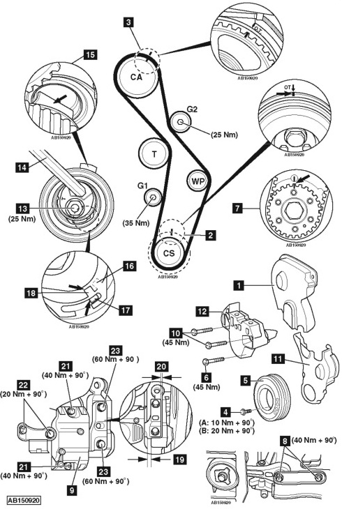
- Ensure timing marks aligned [2] & [3] .
- Remove:
- Crankshaft pulley bolts [4] .
- Crankshaft pulley [5] .
- Timing belt lower cover bolts.
- RH engine mounting bracket bolt [6] .
- Ensure timing marks aligned [3] .
- Mark crankshaft sprocket and backplate with paint [7] .
- Remove engine steady bar bolts [8] .
- Raise engine.
- Remove:
- RH engine mounting [9] .
- RH engine mounting bracket bolts [10] .
- Timing belt lower cover [11] .
- RH engine mounting bracket [12] .
- Slacken tensioner nut [13] .
- Turn tensioner away from belt. Use Allen key [14] . Lightly tighten nut [13] .
- Remove timing belt.NOTE: Mark direction of rotation on belt with chalk if belt is to be reused.
Installation
-
- NOTE: Engine must be COLD.
- Ensure camshaft sprocket timing marks aligned [3] .
- Ensure crankshaft sprocket timing mark aligned [7] .
- Fit timing belt in following order:
- Crankshaft pulley.
- Guide pulley (G1).
- Tensioner pulley.
- Camshaft sprocket.
- Water pump sprocket.
- Guide pulley (G2).
NOTE: If reusing old belt, observe direction of rotation marks on belt.
- Ensure tensioner retaining lug located in slot in cylinder head [15] .
NOTE: Ensure belt is taut between sprockets on non-tensioned side. - Slacken tensioner pulley nut [13] .
- Turn tensioner clockwise until notch [16] is above lug [17] in baseplate. Use Allen key [14] .
- Release tension on belt.
- Turn tensioner slowly clockwise until notch aligned with lug in baseplate [17] & [18] . Use Allen key [14] .
- Tighten tensioner pulley nut [13] . Tightening torque: 25 Nm.
- Turn crankshaft slowly two turns clockwise until timing marks aligned [3] & [7] .
NOTE: Turn crankshaft last 45° smoothly without stopping. - Ensure timing marks aligned [3] & [7] .
- Ensure notch [18] aligned with lug [17] in baseplate.
- If not: Repeat tensioning procedure.
- Install:
- Timing belt lower cover [11] .
- RH engine mounting bracket [12] .
- Tighten RH engine mounting bracket bolts [10] . Tightening torque: 45 Nm.
- Lower engine.
- Tighten RH engine mounting bracket bolt [6] . Tightening torque: 45 Nm.
NOTE: RH engine mounting bracket bolt [6] is 25 mm shorter than the other bolts [10] . - Install:
- Crankshaft pulley [5] .
- Crankshaft pulley bolts [4] . Use new bolts.
- Tighten crankshaft pulley bolts [4] . Tightening torque:
Except AXX/BPY/BWA – A: 10 Nm + 90°.
AXX/BPY/BWA – B: 20 Nm + 90°. - Ensure timing marks aligned [2] & [3] .
- Fit and align RH engine mounting [9] :
- Engine mounting clearance: 10 mm minimum [19] .
- Ensure engine mounting aligned parallel with engine mounting bracket [20] .
- Tighten:
- Engine mounting bolts [21] . Tightening torque: 40 Nm + 90°. Use new bolts.
- Engine mounting bolts [22] . Tightening torque: 20 Nm + 90°. Use new bolts.
- Engine mounting bolts [23] . Tightening torque: 60 Nm + 90°. Use new bolts.
- Install components in reverse order of removal.
- Tighten engine steady bar bolts [8] . Tightening torque: 40 Nm + 90°. Use new bolts.
- Refill cooling system.