Audi A4 (B6) 1.9 TDI 2001 cambelt change instructions and replacement inteval. Full guide!
Special tools
- Camshaft locking tool – No.3359.
- Crankshaft sprocket locking tool – No.T10050.
- Support guides – No.3369.
- Tensioner locking tool – No.T10008.
- Two-pin wrench – No.3387.
- Viscous fan pulley holding tool – No.3212. 4 mm drill bit.
Special precautions
- Disconnect battery earth lead.
- DO NOT turn crankshaft or camshaft when timing belt removed.
- Remove glow plugs to ease turning engine.
- Turn engine in normal direction of rotation (unless otherwise stated).
- DO NOT turn engine via camshaft or other sprockets.
- Observe all tightening torques.
Repair times – hrs
| Camshaft drive belt/chain – R & I | 2,60 |
| Camshaft drive belt/chain, AT – R & I | 2,60 |
Valve timing procedures
Removal
- Move radiator support panel into service position:
- Remove front bumper.
- Remove air intake pipe between front panel and air filter.
- Remove front panel bolts [1] & [2] .
- Install support guides No.3369 in front panel [3] .
- Slide front panel forward.
- Raise and support front of vehicle.
- Disconnect exhaust pipe for auxiliary heater from engine undershield (if fitted).
- Remove:
- Engine top cover.
- Engine undershield.
- Auxiliary drive belt.
- Cooling fan assembly. Use tool No.3212.
- Auxiliary drive belt tensioner.
- Bolts for coolant pipe brackets (if required).
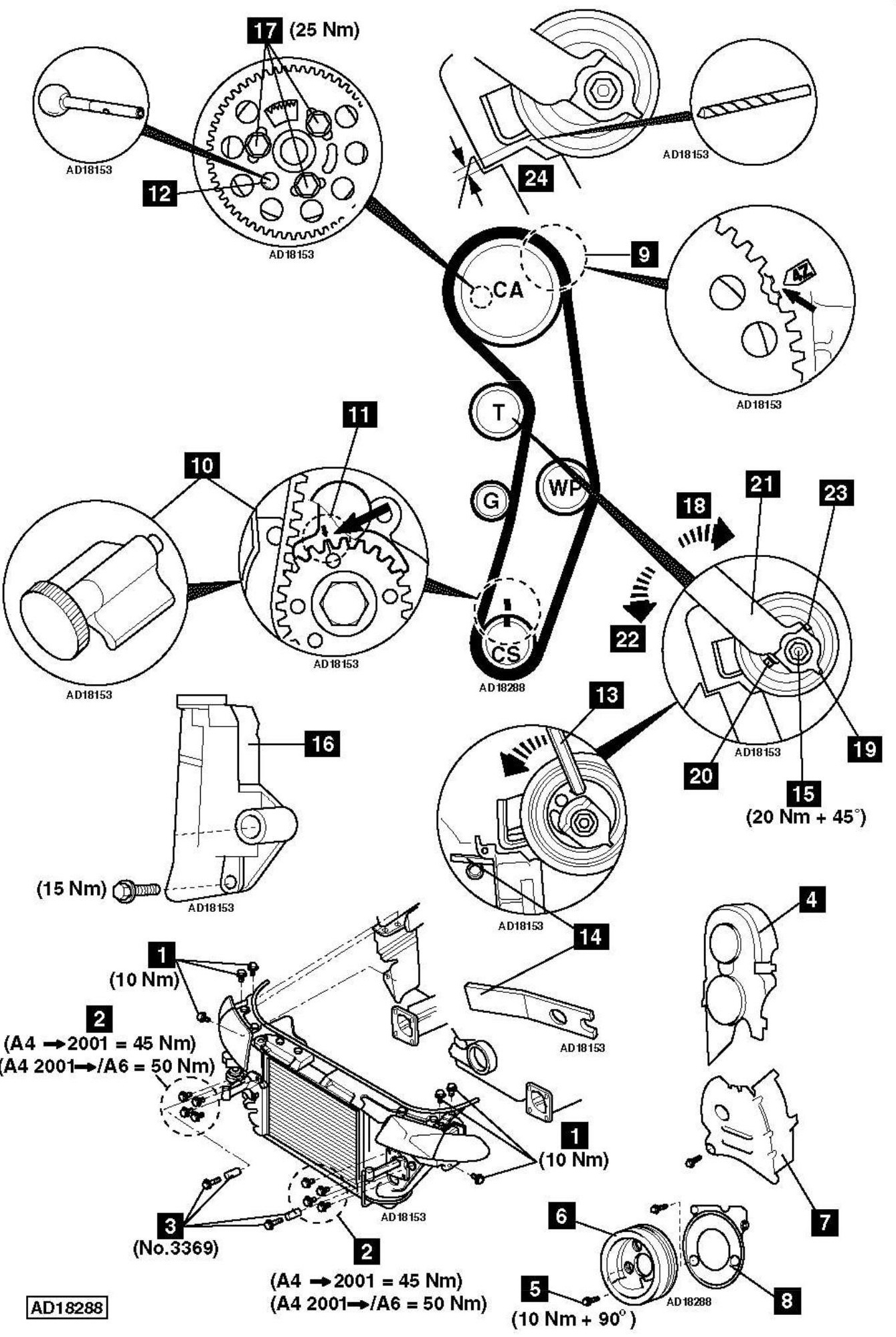
- Timing belt upper cover [4] .
- Move turbocharger (TC) wastegate regulating valve.
- Remove:
- Crankshaft pulley bolts [5] .
- Crankshaft pulley [6] .
- Timing belt centre cover [7] .
- Timing belt lower cover [8] .
- Turn crankshaft clockwise to TDC on No.1 cylinder. Ensure timing mark aligned with notch on camshaft sprocket hub [9] .
NOTE: Notch located behind camshaft sprocket teeth. - Lock crankshaft sprocket [10] . Use tool No.T10050.
- Ensure timing marks aligned [11] .
- Lock camshaft [12] . Use tool No.3359.
- Fully insert Allen key into tensioner pulley [13] .
- Turn tensioner pulley slowly anti-clockwise until locking tool can be inserted [14] . Tool No.T10008.
- Slacken tensioner nut [15] .
- Remove:
- Automatic tensioner unit [16] .
- Timing belt.
Installation
- Ensure camshaft locked with tool [12] . Tool No.3359.
- Ensure crankshaft sprocket locking tool located correctly [10] . Tool No.T10050.
- Ensure timing marks aligned [11] .
- Ensure automatic tensioner unit locked with tool [14] . Tool No.T10008.
- Slacken camshaft sprocket bolts [17] .
- Turn camshaft sprocket fully clockwise in slotted holes. Tighten bolts finger tight [17] .
- Turn tensioner pulley slowly clockwise [18] until lug [19] just reaches stop [20] . Use tool No.3387 [21] .
- Fit timing belt in following order:
- Camshaft sprocket.
- Tensioner pulley.
- Crankshaft sprocket.
- Water pump sprocket.
- Install automatic tensioner unit [16] .
- Turn tensioner pulley slowly anti-clockwise [22] (lug [19] moves towards stop [23] ). Use tool No.3387 [21] .
- Remove locking tool without force [14] .
NOTE: Ensure two-pin wrench remains in position. - Allow tensioner pulley to turn back slowly [21] (lug [19] moves towards stop [20] ) until dimension [24] is 4±1 mm. Use drill bit.
NOTE: Engine must be COLD. - Tighten tensioner nut [15] . Tightening torque: 20 Nm + 45°.
- Tighten camshaft sprocket bolts [17] . Tightening torque: 25 Nm.
- Remove:
- Camshaft locking tool [12] .
- Crankshaft sprocket locking tool [10] .
- Drill bit.
- Turn crankshaft slowly two turns clockwise to TDC on No.1 cylinder.
- Ensure dimension [24] is 4±1 mm. Use drill bit.
- If not: Slacken tensioner nut [15] . Turn tensioner pulley until dimension as specified [24] . Tighten tensioner nut [15] . Tightening torque: 20 Nm + 45°.
- Lock crankshaft sprocket [10] . Use tool No.T10050.
- Ensure timing marks aligned [11] .
- Ensure camshaft locking tool can be inserted easily [12] . Tool No.3359.
- If not:
- Slacken camshaft sprocket bolts [17] .
- Turn sprocket hub until locking tool can be inserted [12] .
- Tighten bolts [17] . Tightening torque: 25 Nm.
- Remove locking tools [10] & [12] .
- Turn crankshaft slowly two turns clockwise to TDC on No.1 cylinder.
- Ensure locking tools can be fitted correctly [10] & [12] .
- Remove:
- Camshaft locking tool [12] .
- Crankshaft locking tool [10] .
- Drill bit.
- Install components in reverse order of removal.
- Tighten crankshaft pulley bolts [5] . Tightening torque: 10 Nm + 90°. Use new bolts.