Renault Scenic 2.0 16V 2003 cambelt change instructions and replacement inteval. Full guide!
Special tools
- Crankshaft timing pin – Renault No.Mot.1054.
- Camshaft setting bar – Renault No.Mot.1496.
- Camshaft adjusting wrench – Renault No.Mot.799-01.
- Camshaft locking tool – Renault No.Mot.1509/01.
Special precautions
- Disconnect battery earth lead.
- DO NOT turn crankshaft or camshaft when timing belt removed.
- Remove spark plugs to ease turning engine.
- Turn engine in normal direction of rotation (unless otherwise stated).
- DO NOT turn engine via camshaft or other sprockets.
- Observe all tightening torques.
Repair times – hrs
| Camshaft drive belt/chain – R & I | 4,70 |
Valve timing procedures
Removal
NOTE: If timing belt is excessively noisy between idle and 2000 rpm a modified timing belt, tensioner pulley and guide pulleys should be fitted. Refer to a Renault dealer.
WARNING: Engines with variable valve timing: Mark camshaft sprockets and camshaft adjusters with chalk or paint prior to timing belt removal to assist alignment on installation.
- Raise and support front of vehicle.
- Remove:
- Engine top cover.
- RH front wheel.
- RH splash guard.
- Auxiliary drive belt.
NOTE: Auxiliary drive belt(s), tensioner pulley and guide pulley(s) MUST be replaced.
- Support engine.
- Remove:
- RH engine mounting.
- Blanking plugs from rear of camshafts.
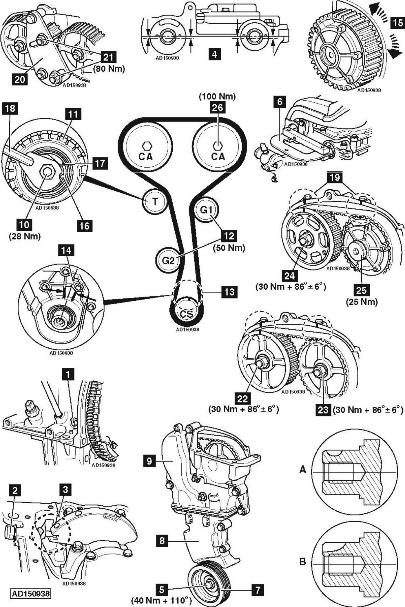
- Blanking plug from cylinder block [1] .
- Turn crankshaft clockwise until grooves in rear of camshafts are just before horizontally aligned position.
NOTE: Grooves located below cylinder head upper face. - Insert timing pin through hole in cylinder block and into crankshaft [2] . Tool No.Mot.1054.
- Turn crankshaft slightly clockwise until timing pin locates in crankshaft [3] . Tool No.Mot.1054.
- NOTE: Ensure timing pin not inserted into crankshaft web balance hole [3] .
- Ensure grooves in rear of camshafts horizontally aligned [4] .
- Lock flywheel with large screwdriver. Slacken crankshaft pulley bolt [5] .
- Fit setting bar to rear of camshafts [6] . Tool No.Mot.1496.
- Remove:
- Crankshaft pulley bolt [5] .
- Crankshaft pulley [7] .
- Timing belt covers [8] & [9] .
- Slacken tensioner nut [10] .
- Allow tensioner pulley to move away from belt.
- Remove:
- Tensioner nut [10] .
- Tensioner pulley [11] .
- Guide pulleys (G1 & G2) [12] .
- Timing belt.
NOTE: DO NOT allow crankshaft sprocket to fall off crankshaft.
Installation
NOTE: Timing belt, tensioner pulley and guide pulleys MUST be replaced.
NOTE: There are two types of crankshaft fitted, type A and type B.
- Ensure timing pin located correctly in crankshaft [3] .
- Ensure grooves in rear of camshafts horizontally aligned [4] . If not: Turn camshafts. Use tool No.Mot.799-01.
- Ensure setting bar fitted correctly [6] .
- Ensure crankshaft keyway [13] located centrally between lugs on engine front housing [14] .
- Fit new guide pulleys (G1 & G2) [12] . Tighten bolts to 50 Nm.
- Fit new tensioner pulley [11] . Temporarily tighten nut to 7 Nm [10] .NOTE: Ensure lug on rear of tensioner pulley located in groove in cylinder head.
- Crankshaft type A:
- Remove crankshaft sprocket. Degrease sprocket. Degrease end of crankshaft. Refit crankshaft sprocket.
NOTE: F4R engines with variable valve timing: Ensure inlet camshaft VVT unit is locked within inlet camshaft sprocket (it should not be possible to rotate VVT unit to the left or right [15] ). If not: Replace VVT unit.
- Fit timing belt in anti-clockwise direction, starting at crankshaft sprocket. Ensure belt is taut on non-tensioned side.
- Fit new crankshaft pulley [7] .
- Fit new crankshaft pulley bolt [5] .
- Temporarily tighten crankshaft pulley bolt [5] . Leave 2-3 mm clearance between bolt contact face and crankshaft pulley [7] .
- Slacken tensioner nut [10] . Turn tensioner pulley clockwise until tensioner marks aligned [16] & [17] . Use 6 mm Allen key [18] .
- Temporarily tighten tensioner nut [10] . Tightening torque: 7 Nm.
- Mark camshaft sprockets and cylinder head with paint or chalk where indicated [19] .
- Lock flywheel with large screwdriver. Temporarily tighten crankshaft pulley bolt [5] . Tightening torque: 20 Nm.
- Remove timing pin [2] .
- Remove setting bar [6] .
- Lock flywheel with large screwdriver. Tighten crankshaft pulley bolt [5] . Tightening torque: 40 Nm + 110°.
- Crankshaft type B:
- Remove crankshaft sprocket. Degrease sprocket. Degrease end of crankshaft.
NOTE: F4R engines with variable valve timing: Ensure inlet camshaft VVT unit is locked within inlet camshaft sprocket (it should not be possible to rotate VVT unit to the left or right [15] ). If not: Replace VVT unit.
- Fit camshaft locking tool [20] . Tool No.Mot.1509/01.
- Tighten camshaft locking tool nuts [21] . Tightening torque: 80 Nm.
- F4P: Remove nut of each camshaft sprocket [22] & [23] .
- F4R: Remove exhaust camshaft sprocket nut [24] .
NOTE: Replace camshaft stud if loosened when removing nut.
- F4R: Remove blanking plug from inlet camshaft sprocket [25] .
- F4R: Remove inlet camshaft sprocket bolt [26] .
- Remove locking tool [20] .
- Remove camshaft sprockets.
- Degrease ends of camshafts and camshaft sprockets.
- F4P: Install camshaft sprockets. Finger tighten nut of each camshaft sprocket [22] & [23] .
- F4R: Install camshaft sprockets. Finger tighten nut and bolt of each camshaft sprocket [24] & [26] .
- Fit crankshaft sprocket.
- Fit timing belt.
- Slacken tensioner nut [10] . Turn tensioner pulley clockwise until tensioner marks aligned [16] & [17] . Use 6 mm Allen key [18] .
- Temporarily tighten tensioner nut [10] . Tightening torque: 7 Nm.
- Fit camshaft locking tool [20] .
- Tighten camshaft locking tool nuts [21] . Tightening torque: 80 Nm.
- F4P: Temporarily tighten nuts of each camshaft sprocket [22] & [23] . Tightening torque: 30 Nm.
- F4R: Temporarily tighten nut and bolt of each camshaft sprocket [24] & [26] . Tightening torque: 30 Nm.
- Remove locking tool [20] .
- Remove setting bar [6] .
- Remove timing pin [2] .
- Mark camshaft sprockets and cylinder head with paint or chalk where indicated [19] .
- Turn crankshaft two turns clockwise until just before setting position [19] .
- Insert timing pin through hole in cylinder block and into crankshaft [2] .
- Turn crankshaft slightly clockwise. Ensure timing pin located correctly in crankshaft [3] .
NOTE: Ensure timing pin not inserted into crankshaft web balance hole.
- Ensure setting position marks aligned [19] .
- Ensure tensioner pulley marks aligned [16] & [17] . If not: Repeat tensioning procedure.
- Tighten tensioner nut [10] . Tightening torque: 28 Nm.
- Fit setting bar [6] .
- Fit locking tool [20] .
- Tighten camshaft locking tool nuts [21] . Tightening torque: 80 Nm.
- F4P: Fit new nuts to camshaft sprockets [22] & [23] . Tightening torque: 30 Nm + 86°±6°.
- F4R: Fit new nut to exhaust camshaft sprocket [24] . Tightening torque: 30 Nm + 86°±6°.
- F4R: Fit new bolt to inlet camshaft sprocket [26] . Tightening torque: 100 Nm.
- F4R: Fit blanking plug to inlet camshaft sprocket [25] . Tightening torque: 25 Nm.
- Remove locking tool [20] .
- Remove setting bar [6] .
- Remove timing pin [2] .
- Fit new crankshaft pulley [7] .
- Fit new crankshaft pulley bolt [5] .
- Lock flywheel with large screwdriver. Tighten crankshaft pulley bolt [5] . Tightening torque: 40 Nm + 110°.
- All engines:
- Turn crankshaft two turns clockwise until just before setting position [19] .
- Insert timing pin through hole in cylinder block and into crankshaft [2] .
- Turn crankshaft slightly clockwise. Ensure timing pin located correctly in crankshaft [3] .NOTE: Ensure timing pin not inserted into crankshaft web balance hole.
- Ensure camshaft setting bar can be fitted easily [6] .
- Ensure tensioner pulley marks aligned [16] & [17] . If not: Repeat tensioning procedure.
- Tighten tensioner nut [10] . Tightening torque: 28 Nm.
- Remove:
- Timing pin [2] .
- Setting bar [6] .
- Refit blanking plug [1] .
- Fit new blanking plugs to rear of camshafts.NOTE: DO NOT start engine without auxiliary drive belt fitted as damage may occur to crankshaft pulley.
- Install components in reverse order of removal.