Opel Meriva 1.7 CDTi 2014 cambelt change instructions and replacement inteval. Full guide!
Special tools
- Except Astra-J/Mokka: Auxiliary drive belt tensioner locking tool – Kent Moore No.KM-6130.
- Astra-J/Mokka: Auxiliary drive belt tensioner adjusting tool – No.EN-913-A.
- Astra-J/Mokka: Auxiliary drive belt tensioner locking tool – No.EN-48952.
Special precautions
- Disconnect battery earth lead.
- DO NOT turn crankshaft or camshaft when timing belt removed.
- Remove glow plugs to ease turning engine.
- Turn engine in normal direction of rotation (unless otherwise stated).
- DO NOT turn engine via camshaft or other sprockets.
- Observe all tightening torques.
Repair times – hrs
| Camshaft drive belt/chain – C & A | 1,40 |
| Camshaft drive belt/chain – R & I | 1,50 |
Valve timing procedures
Removal
- Raise and support vehicle.
- Remove:
- Engine top cover.
- Air filter housing and air intake hose.
- Engine undershield.
- RH front wheel.
- RH inner wing panel.
- Turn auxiliary drive belt tensioner to release tension on belt. Use ring spanner or tool No.EN-913-A.
- Lock auxiliary drive belt tensioner. Use tool No.EN-48952 or No.KM-6130.
- Remove:
- Auxiliary drive belt.
- NOTE: Mark direction of rotation on belt with chalk if belt is to be reused.
- Crankshaft pulley bolts [1] .
- Crankshaft pulley [2] .
- Support engine.
- Remove:
- RH engine mounting.
- RH engine mounting bracket.
- Camshaft position (CMP) sensor.
- Timing belt upper cover [3] .
- Timing belt lower cover [4] .
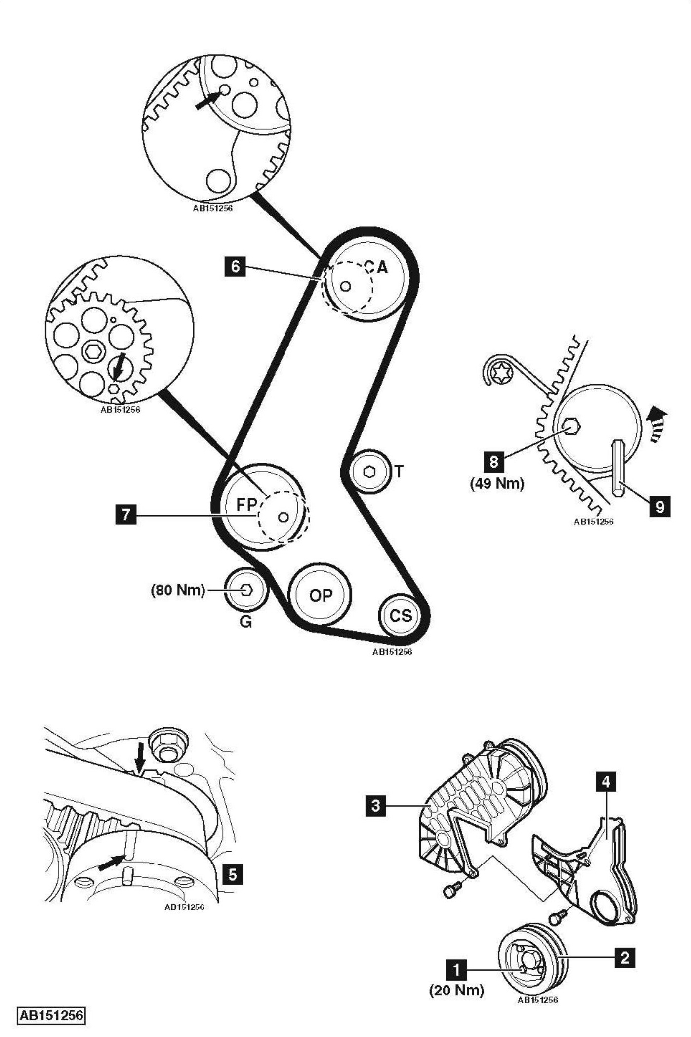
- Turn crankshaft to TDC on No.1 cylinder. Ensure timing marks aligned [5] .
- Ensure camshaft sprocket aligning hole at 8 o’clock position.
- If not: Turn crankshaft one turn clockwise.
- Screw suitable locking bolts into camshaft sprocket and high-pressure fuel pump sprocket [6] & [7]
- Slacken tensioner bolt [8] .
- Turn tensioner pulley 90° anti-clockwise. Use Allen key [9] . Lightly tighten bolt [8] .
- Remove timing belt.
NOTE: Mark direction of rotation on belt with chalk if belt is to be reused.
Installation
- Ensure locking bolts located correctly [6] & [7] .
- Ensure crankshaft sprocket mark aligned with notch [5] .
- Check tensioner pulley and guide pulley for smooth operation.
- Fit timing belt in clockwise direction, starting at crankshaft sprocket. Ensure belt is taut between sprockets.
NOTE: Ensure directional arrows point in direction of rotation. - Slacken tensioner bolt [8] .
- Allow tensioner to tension belt.
- Tighten tensioner bolt [8] . Tightening torque: 49 Nm.
- Remove locking bolts from sprockets [6] & [7] .
- Turn crankshaft 2 turns clockwise to TDC on No.1 cylinder.
- Ensure crankshaft sprocket mark aligned with notch [5] .
- Ensure locking bolts can be installed [6] & [7] .
- If not: Repeat installation procedure.
- Remove locking bolts [6] & [7] .
- Install components in reverse order of removal.
- Tighten crankshaft pulley bolts [1] . Tightening torque: 20 Nm.
NOTE: Observe direction of rotation marks on auxiliary drive belt.
NOTE: If battery has been disconnected, re-initialization of window and sunroof motors and steering position sensor may be required.