Replacement Interval Guide
- Renault recommend:
- 6,000 mile service intervals – replacement every 72,000 miles or 5 years (tensioner pulley must also be replaced).
- 10,000 mile service intervals – replacement every 70,000 miles or 5 years (tensioner pulley must also be replaced).
- 12,000/18,000 mile service intervals – replacement every 72,000 miles or 5 years (tensioner pulley must also be replaced).
- The previous use and service history of the vehicle must always be taken into account.
Check For Engine Damage
CAUTION: This engine has been identified as an INTERFERENCE engine in which the possibility of valve-to-piston damage in the event of a timing belt failure is MOST LIKELY to occur. A compression check of all cylinders should be performed before removing the cylinder head(s).
Repair Times – hrs
| Remove & install: | |
|---|---|
| Twingo | 1,90 |
| RH: Clio (→05/98) | 1,80 |
| RH: Clio (06/98→) | 2,00 |
| LH: Clio/Symbol/Thalia (→05/98) | 1,80 |
| LH: Clio/Symbol/Thalia (06/98→) | 2,00 |
| Kangoo | 2,00 |
Special Tools
- TDC timing pin – Renault No.Mot.1054.
- Tensioner spanner – Renault No.Mot.1135-01.
- Tensioning tool – Renault No.Mot.1386.
- Tension gauge – Renault No.Mot.1715.
Special Precautions
- Disconnect battery earth lead.
- DO NOT turn crankshaft or camshaft when timing belt removed.
- Remove spark plugs to ease turning engine.
- Turn engine in normal direction of rotation (unless otherwise stated).
- DO NOT turn engine via camshaft or other sprockets.
- Observe all tightening torques.
Removal
- Raise and support front of vehicle.
- Remove:
- Engine undershield (if fitted).
- RH front wheel.
- RH splash guard.
- Auxiliary drive belt(s).NOTE: Auxiliary drive belt(s), tensioner pulley and guide pulley(s) MUST be replaced.
- Support engine.
- Remove:
- RH engine mounting intermediate bracket.
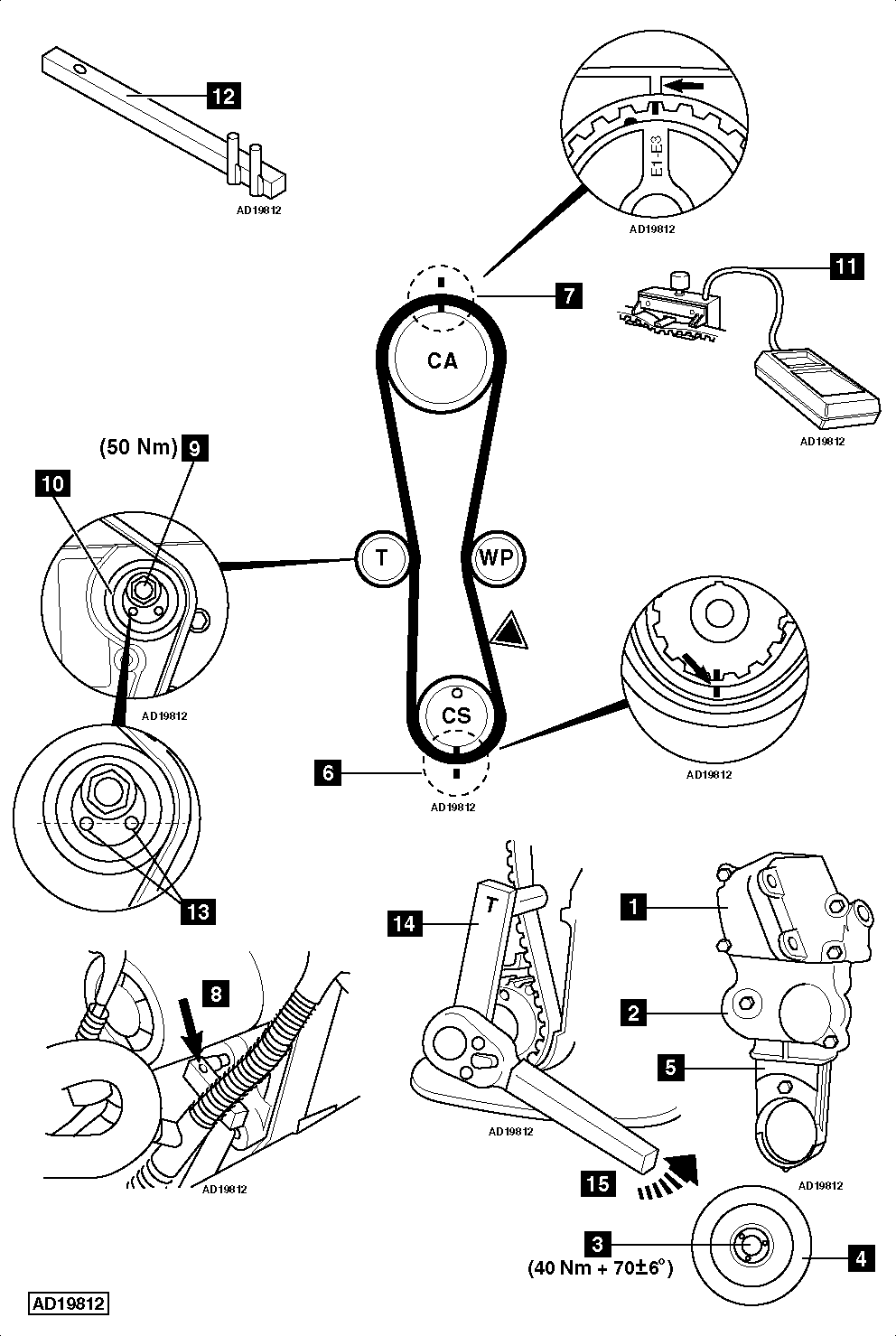
- RH engine mounting bracket [1] .
- Timing belt upper cover [2] .
- Crankshaft pulley centre bolt [3] .
- Crankshaft pulley [4] .
- Timing belt lower cover [5] .
- Temporarily fit crankshaft pulley centre bolt [3] .
- Turn crankshaft to TDC on No.1 cylinder.
- Ensure timing marks aligned [6] & [7] .NOTE: Camshaft sprocket has multiple markings. Use rectangular timing mark adjacent to ‘E1-E3’ lettering.
- Insert timing pin in flywheel [8] . Tool No.Mot.1054.
- Slacken tensioner pulley nut [9] .
- Remove:
- Timing belt.
- Tensioner pulley nut [9] .
- Tensioner pulley [10] .
- Crankshaft pulley centre bolt [3] .
Installation
NOTE: Timing belt and tensioner pulley MUST be replaced.
- Ensure timing marks aligned [6] & [7] .
- Ensure timing pin inserted in flywheel [8] .
- Remove crankshaft sprocket. Degrease sprocket. Degrease end of crankshaft. Refit crankshaft sprocket.WARNING: Failure to degrease components may lead to sprocket slipping on crankshaft, resulting in severe engine damage.
- Fit new tensioner pulley [10] .
- Temporarily tighten tensioner pulley nut [9] .
- Fit crankshaft pulley centre bolt [3] . Tightening torque: 40 Nm + 70±6°.
- Fit timing belt in anti-clockwise direction, starting at crankshaft sprocket.
- Ensure marks on belt aligned with marks on sprockets.
- Ensure belt is taut between sprockets.
- Attach tension gauge to belt at
 . Tool No.Mot.1715 [11] .
 - Slacken tensioner pulley nut [9] .
- Turn tensioner anti-clockwise until tension gauge indicates 145±5 Hz. Use tool No.Mot.1135-01 [12] .
- Tighten tensioner pulley nut [9] . Tightening torque: 50 Nm.
- Remove tension gauge [11] .
- Remove timing pin [8] .
- Turn crankshaft six turns clockwise to TDC on No.1 cylinder.
- Ensure timing pin can be inserted in flywheel [8] .
- Ensure timing marks aligned [6] & [7] .
- Slacken tensioner pulley nut [9] .
- Turn tensioner until holes are horizontal [13] . Use tool No.Mot.1135-01 [12] .
- Tighten tensioner pulley nut [9] . Tightening torque: 50 Nm.
- Remove timing pin [8] .
- Turn crankshaft six turns clockwise to TDC on No.1 cylinder.
- Ensure timing pin can be inserted in flywheel [8] .
- Ensure timing marks aligned [6] & [7] .
- Fit tensioning tool [14] . Tool No.Mot.1386.
- Apply anti-clockwise torque of 10 Nm [15] .
- Remove tensioning tool [14] .
- Attach tension gauge to belt at [11] .
- Tension gauge should indicate 145±5 Hz.
- If tension not as specified: Adjust tensioner manually. Use tool No.Mot.1135-01 [12] .
- Tighten tensioner pulley nut [9] . Tightening torque: 50 Nm.
- Remove timing pin [8] .
- Remove crankshaft pulley centre bolt [3] .
- Fit:
- Timing belt lower cover [5] .
- Crankshaft pulley [4] .
- Crankshaft pulley centre bolt [3] . Tightening torque: 40 Nm + 70±6°. Use new bolt.
NOTE: DO NOT start engine without auxiliary drive belt fitted as damage may occur to crankshaft pulley.
- Install components in reverse order of removal.