Mercedes-Benz E200 W212 1.8 2010 cambelt change instructions and replacement inteval. Full guide!
Special tools
- Balancer shaft chain link kit – No.602589024000.
- Balancer shaft chain link installer die kit – No.271589026300.
- Camshaft holding tool 1 – No.271589006100.
- Camshaft holding tool 2 (271.820/860 engines) – No.271589006100.
- Chain tensioner drift – No.271589001500.
- Crankshaft holding tool – No.271589004000.
- Crankshaft pulley puller – No.000589883300.
- Flywheel/drive plate holding tool – No.602589004000.
- Open-end spanner – No.271589000100.
- Tensioner rail wedge – No.271589003100.
- Timing chain link kit – No.271589096300.
- Timing chain link separator (item 1) – No.602589023300.
- Timing chain link separator (item 2) – No.602589046300.
- Timing chain link separator (item 3) – No.602589046301.
- Timing chain link installer – No.602589003900.
- Timing chain link installer die kit 1 – No.271589016300.
- Timing chain link installer die kit 2 – No.271589056300.
- Timing chain to camshaft sprocket holder – No.271589014000.
- Tool case – No.602589009800.
Special precautions
- Disconnect battery earth lead.
- Remove spark plugs to ease turning engine.
- Turn engine in normal direction of rotation (unless otherwise stated).
- Observe tightening torques.
- If fitted: Mark position of crankshaft position (CKP) sensor before removal.
- Do NOT turn crankshaft via camshaft or other sprockets.
- Do NOT turn crankshaft or camshaft with timing chain removed.
Valve timing procedures
NOTE: Timing chain can be changed without dismantling engine. Using the tools listed above, the new chain can be linked to the old, passed round the sprockets and then joined.
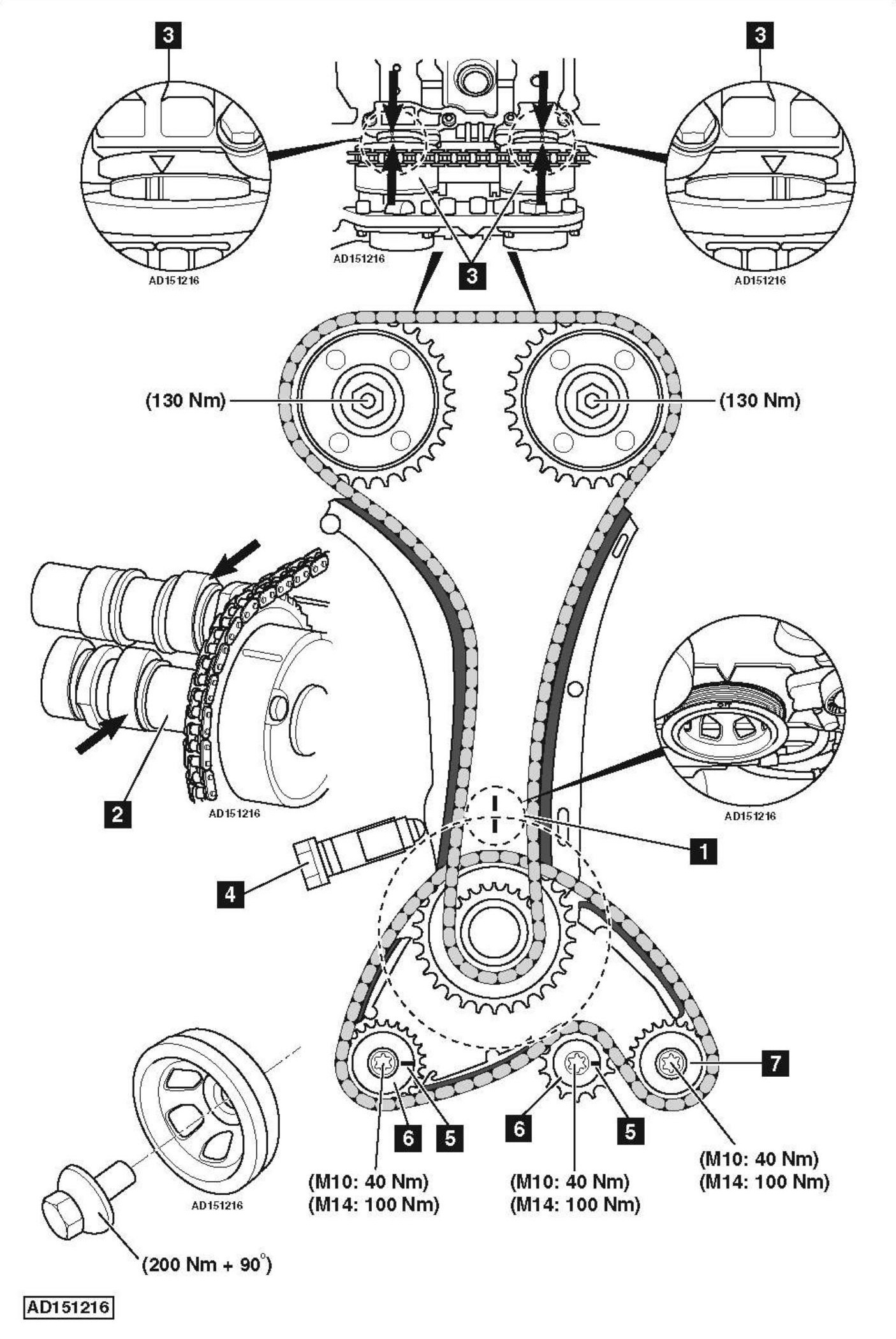
- Engine at TDC on No.1 cylinder [1] .
- Ensure No.1 cylinder camshaft lobes are facing upwards [2] .
- Ensure timing marks on both camshafts aligned [3] .
- Camshaft rotation can be prevented by using camshaft holding tool.
- Remove tensioner assembly before carrying out engine repairs [4] .
- Install tensioner after repairs. Tightening torque: 40 Nm.
- Ensure grooves [5] on sprockets of balancer shafts [6] are horizontal and pointing towards guide sprocket [7] .
-

How to Replace timing belt on Mercedes-Benz E200 W212 1.8 2010