Replacement Interval Guide
- Volkswagen recommend:
- All models
- →2000MY: Check condition and width every 10,000 miles or 12 months, whichever occurs first.
- Lupo
- →2000MY: Replacement every 40,000 miles.
- 2001MY→: Replacement every 60,000 miles.
- Polo–AHG/AKU engines
- →2000MY: Replacement every 40,000 miles.
- 2001MY→: Replacement every 60,000 miles.
- Polo–AGD/ASX engines
- Replacement every 60,000 miles.
NOTE: Volkswagen UK recommend the timing belt is replaced every 4 years if the replacement mileage is not reached.
- The previous use and service history of the vehicle must always be taken into account.
Check For Engine Damage
CAUTION: This engine has been identified as an INTERFERENCE engine in which the possibility of valve-to-piston damage in the event of a timing belt failure is MOST LIKELY to occur. A compression check of all cylinders should be performed before removing the cylinder head.
Repair Times – hrs
| Remove & install | 2,50 |
Special Tools
- Injection pump sprocket locking pin – No.2064.
- Camshaft setting bar – No.2065A.
- Two-pin wrench – No.3387.
Special Precautions
- Disconnect battery earth lead.
- DO NOT turn crankshaft or camshaft when timing belt removed.
- Remove glow plugs to ease turning engine.
- Turn engine in normal direction of rotation (unless otherwise stated).
- DO NOT turn engine via camshaft or other sprockets.
- Observe all tightening torques.
- Check diesel injection pump timing after belt replacement.
Removal
- Support engine.
- Remove:
- Insulation shield.
- Air filter.
- Auxiliary drive belt.
- Lower engine steady bar.
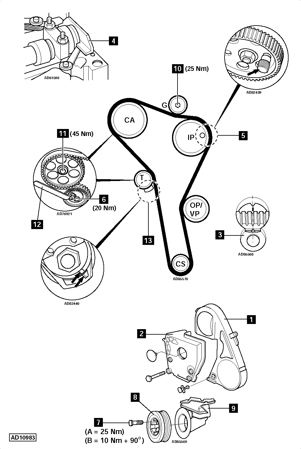
- Timing belt upper cover [1] .
- Cylinder head cover.
- Engine mounting.
- Bracket [2] .
- Turn crankshaft to TDC on No.1 cylinder. Ensure flywheel timing marks aligned [3] .
- Fit setting bar No.2065A to rear of camshaft [4] . Centralise camshaft using feeler gauges.
- Lock injection pump sprocket [5] . Use tool No.2064.
- Slacken tensioner nut [6] . Turn tensioner anti-clockwise away from belt. Lightly tighten nut.
- Lower engine slightly.
- Remove:
- Water pump pulley.
- Crankshaft pulley bolts [7] .
- Crankshaft pulley [8] .
- Auxiliary drive belt tensioner.
- Timing belt lower cover [9] .
- Guide pulley [10] .
- Timing belt.
NOTE: Mark direction of rotation on belt with chalk if belt is to be reused.
Installation
IMPORTANT: Timing belt width must not be less than 21 mm.
- Ensure flywheel timing marks aligned [3] .
- Ensure camshaft setting bar fitted correctly [4] .
- Ensure locking pin located correctly in injection pump sprocket [5] .
- Slacken camshaft sprocket bolt 1/2 turn [11] .
- Loosen sprocket from taper using a drift through hole in timing belt rear cover. Sprocket should turn freely without tilting.
- Fit timing belt in anti-clockwise direction, starting at crankshaft sprocket. Ensure belt is taut between sprockets.
- Remove locking pin from injection pump sprocket [5] .
- Fit guide pulley [10] . Tighten bolt to 25 Nm.
- Slacken tensioner nut [6] .
- Turn automatic tensioner pulley clockwise until notch and raised mark on tensioner aligned [13] . Use tool No.3387 [12] .
- Tighten tensioner nut to 20 Nm [6] .
- Ensure flywheel timing marks aligned [3] .
- Tighten camshaft sprocket bolt to 45 Nm [11] .
- Remove camshaft setting bar [4] .
- Turn crankshaft two turns clockwise until timing marks aligned [3] .
- Ensure camshaft setting bar can be fitted [4] .
- Ensure locking pin can be inserted in injection pump sprocket [5] .
- Apply firm thumb pressure to belt. Tensioner marks should move out of alignment [13] .
- Release thumb pressure from belt. Tensioner marks should realign [13] . If not: Repeat tensioning procedure.
- Install:
- Timing belt lower cover [9] .
- Crankshaft pulley [8] .
- Tighten crankshaft pulley bolts [7] :
- (A) Except Lupo – 25 Nm.
- (B) Lupo – 10 Nm + 90°.
- Install components in reverse order of removal.