Replacement Interval Guide
- Vauxhall recommend replacement as follows:
- →94 MY – replacement every 36,000 miles or 4 years, whichever occurs first.
- 95 MY→ – replacement every 40,000 miles or 4 years, whichever occurs first.
- The previous use and service history of the vehicle must always be taken into account.
Check For Engine Damage
CAUTION: This engine has been identified as an INTERFERENCE engine in which the possibility of valve-to-piston damage in the event of a timing belt failure is MOST LIKELY to occur. A compression check of all cylinders should be performed before removing the cylinder head.
Repair Times – hrs
| Remove & install: | |
|---|---|
| RH: Cavalier/Vectra | 1,40 |
| LH: Vectra | 1,40 |
| Calibra | 1,80 |
| MT | +0,20 |
Special Tools
- RH camshaft locking tool (red) – Kent Moore No.KM-800-1.
- LH camshaft locking tool (green) – Kent Moore No.KM-800-2.
- Crankshaft locking tool – Kent Moore No.KM-800-10.
- Camshaft timing gauge – Kent Moore No.KM-800-20.
- Belt holding tool/wedge (yellow) – Kent Moore No.KM-800-30.
Special Precautions
- Disconnect battery earth lead.
- DO NOT turn crankshaft or camshaft when timing belt removed.
- Remove spark plugs to ease turning engine.
- Turn engine in normal direction of rotation (unless otherwise stated).
- DO NOT turn engine via camshaft or other sprockets.
- Observe all tightening torques.
Removal
- Remove:
- Air filter housing and hoses.
- Engine stabiliser (if fitted).
- Auxiliary drive belt.
- PAS pump pulley.
- Water pump pulley.
- Crankshaft pulley bolts [1] .
- Crankshaft pulley [2] .
- Timing belt cover.
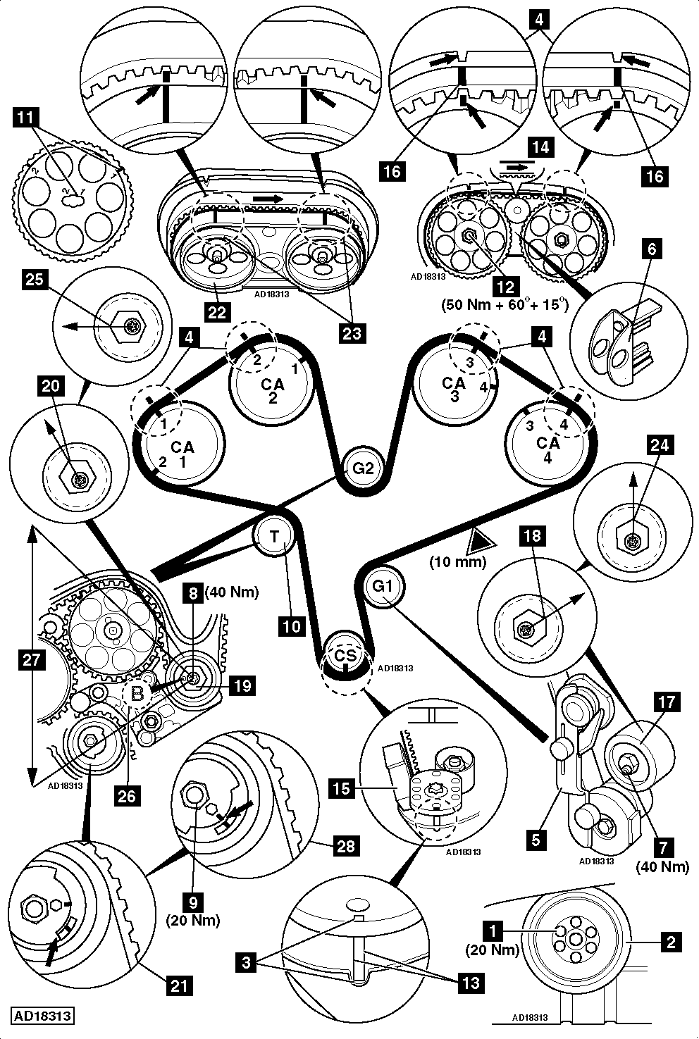
- Turn crankshaft until just before timing marks aligned [3] & [4] .NOTE: Camshaft sprockets fitted to early models may have single timing marks 1, 2, 3 and 4. Ensure sprockets are fitted to their respective camshafts CA1, CA2, CA3 & CA4. On later models (illustrated), camshaft sprockets have dual timing marks. Ensure CA1 sprocket timing mark 1 aligned with timing mark on exhaust camshaft CA1 [4] etc.
- Fit locking tool to crankshaft [5] . Tool No.KM-800-10. Turn crankshaft slowly clockwise until tool arm rests against water pump flange. Secure in position.
- Fit locking tool between camshaft sprockets CA3 & CA4 [6] . Tool No.KM-800-2 (green).
- If locking tool will not fit between camshaft sprockets CA3 & CA4:
- Slacken lower guide pulley bolt [7] .
- Release belt tension slightly by turning lower guide pulley G1.
- Fit locking tool between camshaft sprockets CA1 & CA2 [6] . Tool No.KM-800-1 (red).
- If locking tool will not fit between camshaft sprockets CA1 & CA2:
- Slacken upper guide pulley bolt [8] .
- Release belt tension slightly by turning upper guide pulley G2.
- Slacken tensioner bolt [9] . Turn tensioner pulley fully clockwise to release tension on belt [10] . Lightly tighten bolt.
- If not previously carried out:
- Slacken lower guide pulley bolt [7] .
- Slacken upper guide pulley bolt [8] .
- Remove timing belt.
- Later models: If camshaft sprockets are to be removed: Note position of dowel pins in relation to timing marks.
- Camshaft sprocket CA1 uses No.1 for dowel pin location and timing mark alignment [11] .
- Camshaft sprocket CA2 uses No.2, CA3 uses No.3, CA4 uses No.4.
- Fit new bolts [12] . Tightening torque: 50 Nm + 60° + 15°.
Installation
NOTE: Renew timing belt if it has been disturbed or removed from engine. Ensure dimensions of new belt match original belt.
- Ensure all locking tools located correctly [5] & [6] .
- Ensure engine is cold before installing belt.
- Fit timing belt to crankshaft sprocket. Ensure double lines on belt [13] aligned with crankshaft timing marks [3] .
- Observe direction of rotation marks on belt [14] .
- Wedge belt into position. Use tool No.KM-800-30 [15] .
- Fit timing belt around lower guide pulley G1.
- Fit timing belt to camshaft sprockets CA3 & CA4. Ensure single lines on belt [16] aligned with timing marks [4] . Ensure belt is taut between sprockets.
- Ensure slack at
 does not exceed 10 mm.
 - Fit timing belt around upper guide pulley G2.
- Fit timing belt to camshaft sprockets CA1 & CA2. Ensure single lines on belt [16] aligned with timing marks [4] . Ensure belt is taut between sprockets.
- Fit timing belt around tensioner pulley [10] .
- Turn lower guide pulley [17] anti-clockwise until belt taut between lower guide pulley [17] and camshaft sprocket CA4. Tighten bolt to 40 Nm [7] .
- Tip of the eccentric is positioned at approximately 2 o’clock [18] .
- Turn upper guide pulley [19] anti-clockwise until belt taut between camshaft sprockets CA2 & CA3. Tighten bolt to 40 Nm [8] .
- Tip of the eccentric is positioned at approximately 11 o’clock [20] .
- Slacken tensioner bolt [9] .
- Turn tensioner pulley [10] anti-clockwise as far as it will go [21] to pre-tension belt. Tighten bolt to 20 Nm [9] .
- Remove:
- Locking tools [5] & [6] .
- Belt holding tool [15] .
- Turn crankshaft slowly two turns clockwise until just before timing marks aligned [3] & [4] .NOTE: Belt marks are for installation purposes only. They will no longer align once crankshaft has been turned.
- Fit locking tool to crankshaft [5] . Tool No.KM-800-10. Turn crankshaft slowly clockwise until tool arm rests against water pump flange. Secure in position.
- Ensure timing marks aligned [3] .
- Fit timing gauge to camshaft sprockets CA3 & CA4 [22] . Tool No.KM-800-20.
- Slacken lower guide pulley bolt [7] .
- Turn lower guide pulley [17] anti-clockwise until timing marks on camshaft sprocket and timing gauge aligned [23] . The tip of the eccentric is now positioned at approximately 12 o’clock [24] . Tighten bolt to 40 Nm [7] .
- Fit timing gauge to camshaft sprockets CA1 & CA2 [22] . Tool No.KM-800-20.
- Slacken upper guide pulley bolt [8] .
- Turn upper guide pulley [19] anti-clockwise until timing marks on camshaft sprocket and timing gauge aligned [23] . The tip of the eccentric is now positioned at approximately 9 o’clock [25] . Tighten bolt to 40 Nm [8] .
- If upper guide pulley is marked with the letter ‘B’ [26] , ensure this is positioned within the ‘Safe Zone’ [27] .NOTE: If the letter ‘B’ is NOT within this area, the guide pulley will lock up causing serious engine damage.
- Remove timing gauge [22] .
- Slacken tensioner bolt [9] .
- Turn tensioner pulley clockwise until tensioner marks aligned [28] . Tighten bolt to 20 Nm [9] .
- Remove crankshaft locking tool [5] .
- Turn crankshaft slowly two turns clockwise until just before timing marks aligned [3] & [4] .
- Fit locking tool to crankshaft [5] . Tool No.KM-800-10. Turn crankshaft slowly clockwise until tool arm rests against water pump flange. Secure in position.
- Ensure timing marks aligned [3] .
- Fit timing gauge to camshaft sprockets CA1 & CA2 and CA3 & CA4 in turn [22] . Tool No.KM-800-20.
- Ensure timing marks on camshaft sprocket and timing gauge aligned [23] .
- If necessary: Repeat tensioning and adjustment procedures. Start at lower guide pulley [17] .
- Remove:
- Camshaft timing gauge [22] .
- Crankshaft locking tool [5] .
- Install components in reverse order of removal.NOTE: During removal of timing belt covers the sealing tape may become damaged or detached, resulting in severe engine damage if it comes into contact with timing belt. Ensure sealing tape is secured to timing belt covers with a suitable adhesive and renewed if necessary.
- Tighten crankshaft pulley bolts to 20 Nm [1] .