Replacement Interval Guide
- Vauxhall recommend:
- 2004MY – replacement every 60,000 miles or 6 years (tensioner and guide pulleys must also be replaced).
- 2005MY→ – replacement every 80,000 miles or 8 years (tensioner and guide pulleys must also be replaced).
- The previous use and service history of the vehicle must always be taken into account.
Check For Engine Damage
CAUTION: This engine has been identified as an INTERFERENCE engine in which the possibility of valve-to-piston damage in the event of a timing belt failure is MOST LIKELY to occur. A compression check of all cylinders should be performed before removing the cylinder head.
Repair Times – hrs
| Remove & install | 1,30 |
Special Tools
- Camshaft sprocket locking tool – Kent Moore No.KM-853.
- Engine alignment tool – Kent Moore No.KM-6173.
- Engine support tool – Kent Moore No.KM-6001-A.
Special Precautions
- Disconnect battery earth lead.
- DO NOT turn crankshaft or camshaft when timing belt removed.
- Remove spark plugs to ease turning engine.
- Turn engine in normal direction of rotation (unless otherwise stated).
- DO NOT turn engine via camshaft or other sprockets.
- Observe all tightening torques.
Removal
WARNING: Certain engines require modification to tensioner pulley/guide pulleys due to possible failure. Refer to dealer.
- Remove:
- Air filter housing.
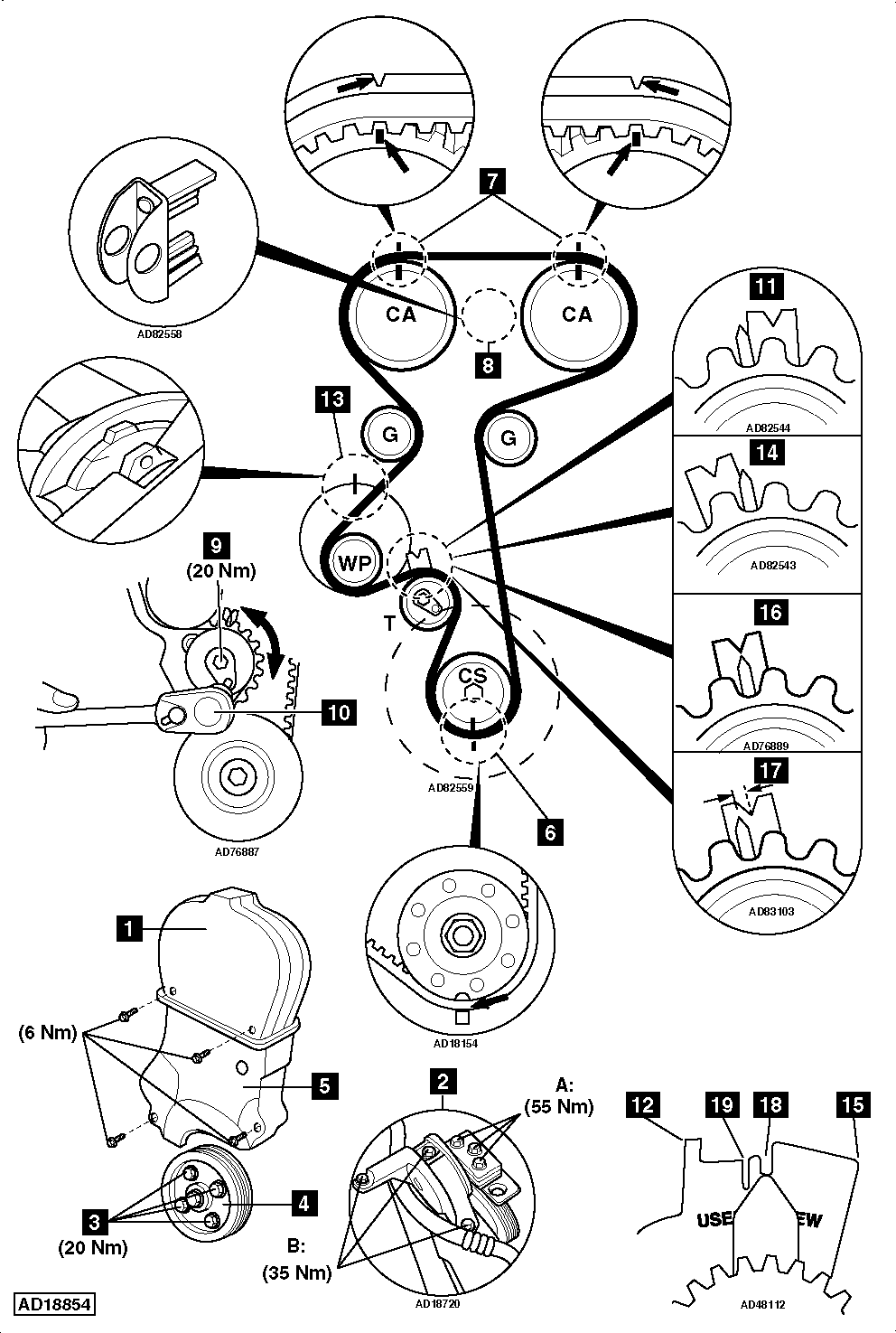
- Timing belt upper cover [1] .
- Mark direction of rotation on auxiliary drive belt with chalk.
- Turn auxiliary drive belt tensioner to release tension on belt. Use ring spanner.
- Remove:
- Auxiliary drive belt.
- Auxiliary drive belt tensioner.
- Raise and support front of vehicle.
- Remove:
- RH front wheel.
- RH inner wing panel.
- Support engine. Tool Nos.KM-6001-A/KM-6173.
- Remove:
- RH engine mounting [2] .
- Crankshaft pulley bolts [3] .
- Crankshaft pulley [4] .
- Timing belt lower cover [5] .
- Camshaft position (CMP) sensor (if fitted).
- Turn crankshaft clockwise to TDC on No.1 cylinder. Ensure crankshaft timing marks aligned [6] .
- Timing marks on camshaft sprockets must be aligned with marks on cylinder head cover [7] .
- Lock camshaft sprockets. Use tool No.KM-853 [8] .
- Slacken tensioner bolt [9] .
- Turn tensioner clockwise until pointer on LH stop. Use Allen key [10] .
- Type 1 – [11] .
- Type 2 – [12] .
- Lightly tighten tensioner bolt [9] .
- Remove timing belt.
NOTE: Mark direction of rotation on belt with chalk if belt is to be reused.
Installation
- Ensure mark on water pump aligned with mark on cylinder block [13] .
- Ensure timing marks aligned [6] & [7] .
- Fit timing belt in anti-clockwise direction, starting at crankshaft sprocket. Ensure belt is taut between sprockets.
- Slacken tensioner bolt [9] .
- Turn tensioner anti-clockwise until pointer on RH stop. Use Allen key [10] .
- Type 1 – [14] .
- Type 2 – [15] .
- Lightly tighten tensioner bolt [9] .
- Remove locking tool from camshaft sprockets [8] .
- Turn crankshaft two turns clockwise. Ensure timing marks aligned [6] & [7] .
- Lock camshaft sprockets. Use tool No.KM-853 [8] .
- Slacken tensioner bolt [9] .
- Turn tensioner clockwise until pointer aligned as follows:
- Type 1:
- New belt – ‘V’ notch in bracket [16] .
- Used belt – LH edge of ‘V’ notch [17] .
- Type 2:
- New belt – ‘NEW’ notch in bracket [18] .
- Used belt – ‘USED’ notch in bracket [19] .
- Lightly tighten tensioner bolt [9] .
- Remove locking tool from camshaft sprockets [8] .
- Turn crankshaft slowly two turns clockwise. Ensure timing marks aligned [6] & [7] .
- Check pointer aligned as follows:
- Type 1:
- New belt – ‘V’ notch in bracket [16] .
- Used belt – LH edge of ‘V’ notch [17] .
- Type 2:
- New belt – ‘NEW’ notch in bracket [18] .
- Used belt – ‘USED’ notch in bracket [19] .
- Tighten tensioner bolt to 20 Nm [9] .
- Install components in reverse order of removal.
- Tighten crankshaft pulley bolts [3] . Tightening torque: 20 Nm.
- Tightening torques:
- A: Engine mounting to bracket – 55 Nm [2] .
- B: Engine mounting to sidemember – 35 Nm [2] .
NOTE: Observe direction of rotation marks on auxiliary drive belt.