Replacement Interval Guide
- Vauxhall recommend replacement every 100,000 miles or 10 years (tensioner pulley and guide pulley must also be replaced).
- The previous use and service history of the vehicle must always be taken into account.
Check For Engine Damage
CAUTION: This engine has been identified as an INTERFERENCE engine in which the possibility of valve-to-piston damage in the event of a timing belt failure is MOST LIKELY to occur. A compression check of all cylinders should be performed before removing the cylinder head.
Repair Times – hrs
| Remove & install: | |
|---|---|
| Astra-H/Zafira-B | 1,30 |
| Vectra-C/Signum | 1,00 |
| Insignia | 1,40 |
Special Tools
- Auxiliary drive belt tensioner locking tool – Kent Moore No.KM-6349.
- Camshaft sprockets locking tool – Kent Moore No.KM-6340.
- Flywheel locking tool – Kent Moore No.KM-6625.
- Tensioner pulley locking pin – Kent Moore No.KM-6333.
Special Precautions
- Disconnect battery earth lead.
- DO NOT turn crankshaft or camshaft when timing belt removed.
- Remove spark plugs to ease turning engine.
- Turn engine in normal direction of rotation (unless otherwise stated).
- DO NOT turn engine via camshaft or other sprockets.
- Observe all tightening torques.
Removal
WARNING: Engines with variable valve timing: Mark camshaft sprockets and camshaft adjusters with chalk or paint prior to timing belt removal to assist alignment on installation.
- Raise and support front of vehicle.
- Remove:
- Engine top cover.
- Air filter housing and hoses.
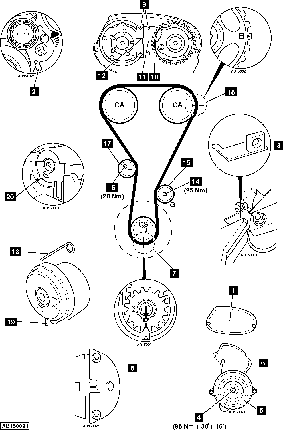
- Timing belt upper cover [1] .
- RH front wheel.
- RH wheel arch liner.
- Support engine.
- Remove RH engine mounting and bracket.
- Mark direction of rotation on auxiliary drive belt with chalk.
- Turn auxiliary drive belt tensioner to release tension on belt. Use ring spanner.
- Lock auxiliary drive belt tensioner [2] . Use tool No.KM-6349.
- Remove:
- Auxiliary drive belt.
- Auxiliary drive belt tensioner.
- Remove bolt from cylinder block. Install flywheel locking tool [3] . Tool No.KM-6625.
- Remove:
- Crankshaft pulley bolt [4] .
- Crankshaft pulley [5] .
- Timing belt lower cover [6] .
- Flywheel locking tool [3] .
- Temporarily fit crankshaft pulley bolt [4] .
- Turn crankshaft clockwise to TDC on No.1 cylinder. Ensure timing marks aligned [7] .
- Remove RH plate from camshaft sprockets locking tool [8] .
- Fit camshaft sprockets locking tool [9] . Tool No.KM-6340.
- Ensure timing mark aligned with groove on camshaft sprockets locking tool [10] & [11] .
- Ensure timing mark on inlet camshaft adjuster is positioned above groove on camshaft sprockets locking tool [12] & [11] .
- Turn tensioner pulley clockwise until locking pin can be inserted [13] . Tool No.KM-6333.
- Remove:
- Guide pulley bolt [14] . Bolt MUST be replaced.
- Guide pulley [15] .
- Timing belt.
- Tensioner pulley locking pin [13] .
- Tensioner pulley bolt [16] .
- Tensioner pulley [17] .
NOTE: Mark direction of rotation on belt with chalk if belt is to be reused.
Installation
NOTE: DO NOT use timing mark ‘B’ [18] .
- Ensure timing marks aligned [7] .
- Fit new tensioner pulley and bolt [17] & [16] . Tightening torque: 20 Nm.
NOTE: New tensioner pulley supplied with locking pin installed [13] . DO NOT remove locking pin until timing belt fitted.
- Ensure tensioner tab [19] engaged in cut-out [20] .
- Fit timing belt in anti-clockwise direction, starting at crankshaft sprocket. Ensure belt is taut between sprockets.
NOTE: New belt supplied from manufacturer with fitting/assembly tool. Remove tool after fitment of belt.
- Fit new guide pulley and bolt [14] & [15] . Tightening torque: 25 Nm.
- Remove:
- Tensioner pulley locking pin [13] .
- Camshaft sprockets locking tool [9] .
- Turn crankshaft slowly two turns in direction of rotation to TDC on No.1 cylinder.
- Ensure timing marks aligned [7] .
- Fit camshaft sprockets locking tool [9] .
- Ensure marks on locking tool aligned [10] & [11] .
- Ensure timing mark on inlet camshaft adjuster is positioned above groove on camshaft sprockets locking tool [12] & [11] .
- Remove:
- Camshaft sprockets locking tool [9] .
- Crankshaft pulley bolt [4] .
- Install components in reverse order of removal.
- Install flywheel locking tool [3] .
- Fit new crankshaft pulley bolt [4] . Tightening torque: 95 Nm + 30° + 15°.
- Remove flywheel locking tool [3] .
- Fit bolt to cylinder block.
NOTE: Observe direction of rotation marks on auxiliary drive belt.