Replacement Interval Guide
- Renault recommend:
- D4Ft 780:
- →2008:
- Replacement every 72,000 miles or 5 years (tensioner pulley must be replaced).
- 01/09-08/09:
- Replacement every 72,000 miles or 6 years (tensioner pulley must be replaced).
- 08/09→:
- Replacement every 75,000 miles or 6 years (tensioner pulley must be replaced).
- D4F 772:
- →2008:
- Replacement every 72,000 miles or 5 years (tensioner pulley must be replaced).
- 2009→:
- Replacement every 72,000 miles or 6 years (tensioner pulley must be replaced).
- The previous use and service history of the vehicle must always be taken into account.
Check For Engine Damage
CAUTION: This engine has been identified as an INTERFERENCE engine in which the possibility of valve-to-piston damage in the event of a timing belt failure is MOST LIKELY to occur. A compression check of all cylinders should be performed before removing the cylinder head(s).
Repair Times – hrs
| Remove & install: | |
|---|---|
| D4F 772 | 1,90 |
| AC | +0,20 |
| D4Ft 780 | 2,40 |
| AC | +0,60 |
Special Tools
- Auxiliary drive belt tension gauge – Renault No.Mot.1505/1715.
- Flywheel timing pin – Renault No.Mot.1054.
- D4F 772: Flywheel locking tool – Renault No.Mot.582-01.
Special Precautions
- Disconnect battery earth lead.
- DO NOT turn crankshaft or camshaft when timing belt removed.
- Remove spark plugs to ease turning engine.
- Turn engine in normal direction of rotation (unless otherwise stated).
- DO NOT turn engine via camshaft or other sprockets.
- Observe all tightening torques.
Removal
- Raise and support front of vehicle.
- Remove:
- RH front wheel.
- RH wheel arch liner.
- Engine lower tie-bar.
- Auxiliary drive belt.
NOTE: Auxiliary drive belt(s), tensioner pulley and guide pulley(s) MUST be replaced.
- Support engine.
- Remove RH engine mounting and bracket.
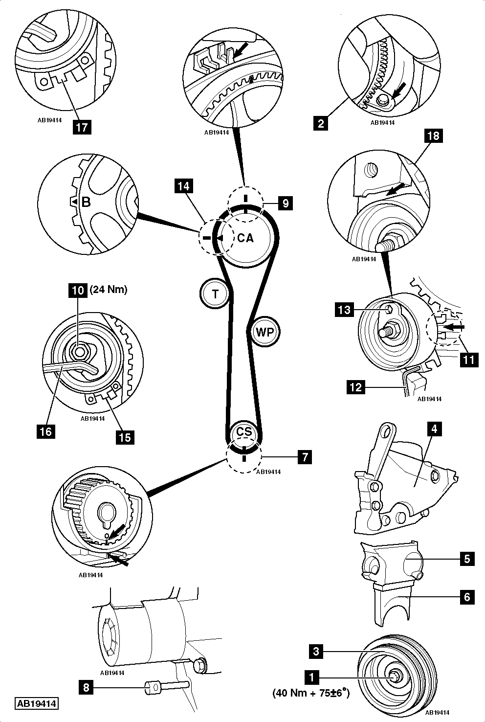
- D4Ft 780: Lock flywheel with large screwdriver. Slacken crankshaft pulley bolt [1] .
- D4F 772: Remove flywheel housing lower cover.
- D4F 772: Lock flywheel. Use tool No.Mot.582-01 [2] . Slacken crankshaft pulley bolt [1] .
- Remove:
- Crankshaft pulley bolt [1] .
- Crankshaft pulley [3] .
- Refit crankshaft pulley bolt [1] .
- Unclip fuel pipe from timing belt upper cover.
- D4Ft 780: Disconnect oil pressure switch wiring connector.
- D4Ft 780: Unclip wiring harness from timing belt upper cover.
- Remove timing belt covers [4] , [5] & [6] .
- Turn crankshaft clockwise until crankshaft sprocket timing marks almost aligned [7] .
- Insert flywheel timing pin [8] . Tool No.Mot.1054.
NOTE: Some models may have a flywheel cover. If this is the case, starter motor and flywheel cover will have to be removed before inserting timing pin.
- Turn crankshaft slightly clockwise until flywheel stops against timing pin [8] .
- Ensure crankshaft sprocket timing marks aligned [7] .
- Ensure camshaft sprocket timing marks aligned [9] .
- Remove:
- Tensioner pulley nut [10] .
- Tensioner pulley.
- Timing belt.
Installation
NOTE: Timing belt, tensioner pulley and guide pulley MUST be replaced.
- Ensure timing pin located correctly [8] .
- Ensure camshaft sprocket timing marks aligned [9] .
- Ensure crankshaft sprocket timing marks aligned [7] .
- Fit new tensioner pulley. Ensure rib on cylinder head positioned between lugs [11] .
- Ensure tensioner pulley locked with pin [12] .
- Finger tighten tensioner pulley nut [10] .
- Ensure tensioner pulley positioned as shown [13] .
- Fit timing belt. Ensure marks on belt aligned with marks on sprockets [7] & [9] . Ensure belt is taut on non-tensioned side.
NOTE: DO NOT use timing mark ‘B’ [14] .
- Remove:
- Timing pin [8] .
- Tensioner pulley locking pin [12] .
- Turn tensioner pulley anti-clockwise until pointer at position shown [15] . Use 6 mm Allen key [16] .
- Tighten tensioner pulley nut [10] . Tightening torque: 24 Nm.
- Turn crankshaft six turns clockwise.
- Insert timing pin in flywheel [8] . Rock crankshaft slightly to ensure timing pin located correctly.
- Ensure timing marks aligned [7] & [9] .
- Remove timing pin [8] .
- Slacken tensioner pulley nut [10] whilst holding 6 mm Allen key [16] .
- Turn tensioner pulley clockwise until pointer in centre position [17] . Tighten tensioner pulley nut [10] . Tightening torque: 24 Nm.
- Ensure tensioner pulley does not touch cylinder head at position shown [18] . If tensioner pulley is touching cylinder head, repeat installation procedure.
- Remove crankshaft pulley bolt [1] .
- Install components in reverse order of removal.
- Fit and align RH engine mounting.
- Tighten crankshaft pulley bolt [1] . Tightening torque: 40 Nm + 75±6°. Use new bolt.