Replacement Interval Guide
- Peugeot recommend:
- Replacement every 84,000 miles or 10 years under normal conditions.
- Replacement every 80,000 miles or 10 years under adverse conditions.
- The previous use and service history of the vehicle must always be taken into account.
- Refer to Timing Belt Replacement Intervals at the front of this manual.
Check For Engine Damage
CAUTION: This engine has been identified as an INTERFERENCE engine in which the possibility of valve-to-piston damage in the event of a timing belt failure is MOST LIKELY to occur. A compression check of all cylinders should be performed before removing the cylinder head(s).
Repair Times – hrs
| Remove & install | 3,10 |
Special Tools
- Auxiliary drive belt tensioner locking tool – No.(-).0189-E.
- Auxiliary drive belt tensioner pulley adjusting tool adaptor – No.(-).0189-W.
- Auxiliary drive belt tensioner pulley adjusting tool – No.(-).0188-Z.
- Camshaft timing pin – No.(-).0194-A.
- Flywheel/drive plate locking tool – No.(-).0189-R.
- Timing belt retaining clip – No.(-).0189-K.
- Tensioner pulley adjusting tool – No.(-).0189-S1.
- Tensioner pulley locking tool – No.(-).0189-S2.
Special Precautions
- Disconnect battery earth lead.
- DO NOT turn crankshaft or camshaft when timing belt removed.
- Remove spark plugs to ease turning engine.
- Turn engine in normal direction of rotation (unless otherwise stated).
- DO NOT turn engine via camshaft or other sprockets.
- Observe all tightening torques.
Removal
WARNING: Engines with variable valve timing: Mark camshaft sprockets and camshaft adjusters with chalk or paint prior to timing belt removal to assist alignment on installation.
- Raise and support front of vehicle.
- Remove:
- Evaporative emission (EVAP) canister purge valve and bracket.
- Engine top cover.
- RH front wheel.
- RH wheel arch liner.
- Engine undershield.
- RH support bracket securing chassis to body.
- Auxiliary drive belt. Use tool Nos.(-).0189-W, (-).0188-Z & (-).0189-E.
- Support engine.
- Remove:
- RH engine mounting.
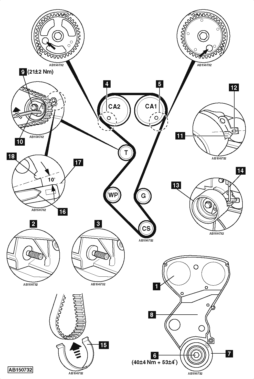
- Timing belt upper cover [1] .
- Turn crankshaft clockwise to setting position.
- Insert flywheel/drive plate locking tool. Tool No.(-).0189-R:
- MT: [2] .
- AT: [3] .
NOTE: Vehicles with AT: Drive plate locking tool will not fit flush in housing.
- Insert timing pins in camshaft sprockets [4] & [5] . Tool No.(-).0194-A.
- Remove:
- Crankshaft pulley bolt [6] .
- Crankshaft pulley [7] .
- Timing belt lower cover [8] .
- Slacken tensioner pulley bolt [9] .
- Turn tensioner pulley clockwise. Use Allen key [10] .
- Remove timing belt.
NOTE: Timing belt must always be renewed once it has been removed.
Installation
- Check tensioner pulley, water pump sprocket and guide pulley for smooth operation. Replace if necessary.
- Ensure flywheel/drive plate locking tool located correctly [2] or [3] .
- Ensure timing pins located correctly [4] & [5] .
- Ensure crankshaft sprocket Woodruff key at 9 o’clock position.
- Turn tensioner pulley clockwise until pointer passes window in baseplate [11] & [12] . Use tool No.(-).0189-S1 [13] .
- Fit locking tool to tensioner pulley [14] . Tool No.(-).0189-S2.
- Remove adjusting tool from tensioner pulley [13] .
- Fit timing belt to crankshaft sprocket.
- Secure belt to crankshaft sprocket with retaining clip. Tool No.(-).0189-K [15] .
- Fit timing belt in following order:
- Guide pulley.
- Camshaft sprocket (CA1).
- Camshaft sprocket (CA2).
- Water pump sprocket.
- Tensioner pulley.
NOTE: Ensure timing belt is fitted flush with sprockets and pulleys.
- Remove tools [15] , [4] & [14] .
- Fit timing belt lower cover [8] .
- Fit crankshaft pulley [7] .
- Clean crankshaft pulley bolt and crankshaft threads.
- Fit crankshaft pulley bolt [6] . Tightening torque: 40±4 Nm + 53±4°.
- Turn tensioner pulley anti-clockwise until pointer [16] at position shown [17] . Use Allen key [10] .
NOTE: The pointer should pass notch [18] by at least 10°. If not, replace tensioner pulley.
- Tighten tensioner pulley bolt [9] . Tightening torque: 21±2 Nm.WARNING: Hold tensioner pulley during tightening to prevent it from turning. If tensioner pulley turns when bolt is tightened, repeat tensioning procedure.
- Remove tools [2] or [3] & [5] .
- Turn crankshaft 10 turns clockwise to setting position.
NOTE: DO NOT allow crankshaft to turn anti-clockwise.
- Insert flywheel/drive plate locking tool [2] or [3] .
- Insert timing pin in inlet camshaft sprocket (CA1) [5] .
- If timing pin cannot be inserted easily, repeat installation and tensioning procedures.
- Slacken crankshaft pulley bolt [6] .
- Slacken tensioner pulley bolt [9] whilst holding Allen key [10] .
- Turn tensioner pulley clockwise until pointer and notch aligned [16] & [18] .
NOTE: If pointer passes notch [18] , repeat tensioning procedure.
- Tighten tensioner pulley bolt [9] . Tightening torque: 21±2 Nm.WARNING: Hold tensioner pulley during tightening to prevent it from turning. If tensioner pulley turns when bolt is tightened, repeat tensioning procedure.
- Fit new crankshaft pulley bolt [6] . Tightening torque: 40±4 Nm + 53±4°.
- Remove tools [2] or [3] & [5] .
- Turn crankshaft 2 turns clockwise to setting position.
NOTE: DO NOT allow crankshaft to turn anti-clockwise.
- Insert timing pin in inlet camshaft sprocket (CA1) [5] .
- Ensure tensioner pulley pointer and notch aligned [16] & [18] . If not, repeat tensioning procedure.
- Remove timing pin from inlet camshaft sprocket (CA1) [5] .
- Install components in reverse order of removal.