Replacement Interval Guide
- Jaguar recommend:
- Replace timing belt every 112,000 miles or 10 years.
- Replace high-pressure fuel pump drive belt every 144,000 miles or 9 years.
- The previous use and service history of the vehicle must always be taken into account.
Check For Engine Damage
CAUTION: This engine has been identified as an INTERFERENCE engine in which the possibility of valve-to-piston damage in the event of a timing belt failure is MOST LIKELY to occur. A compression check of all cylinders should be performed before removing the cylinder head(s).
Repair Times – hrs
| Remove & install: | |
|---|---|
| Timing belt | 4,30 |
| High-pressure fuel pump belt | 2,30 |
Special Tools
- Camshaft sprocket timing pins – No.303-1126.
- Flywheel locking tool – No.303-1117.
- High-pressure fuel pump sprocket locking tool – No.310-212.
Special Precautions
- Disconnect battery earth lead.
- DO NOT turn crankshaft or camshaft when timing belt removed.
- Remove glow plugs to ease turning engine.
- Turn engine in normal direction of rotation (unless otherwise stated).
- DO NOT turn engine via camshaft or other sprockets.
- Observe all tightening torques.
Timing Belt
Removal
- Raise and support front of vehicle.
- Drain coolant.
- Remove:
-
- Engine top cover.
-
- Coolant expansion tank.
-
- Disconnect intercooler intake housing multi-plug.
- Remove:
-
- Intercooler intake housing.
-
- Intercooler intake housing bracket.
-
- Air filter housing and hoses.
-
- Upper fan shroud.
-
- Engine undershields.
-
- Unclip coolant hoses from lower fan shroud.
- Remove:
-
- Lower fan shroud.
-
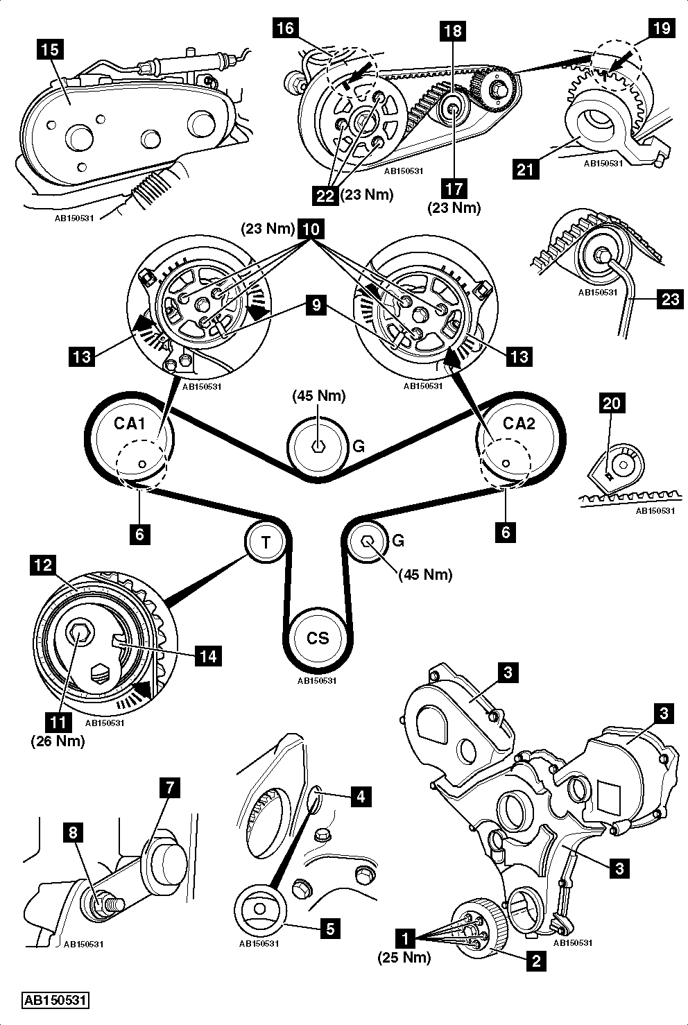
- Crankshaft pulley bolts [1] .
-
- Crankshaft pulley [2] .
-
- Coolant outlet hose from cylinder head.
-
- Auxiliary drive belt.NOTE: Mark direction of rotation on belt with chalk if belt is to be reused.
-
- Auxiliary drive belt tensioner.
-
- Auxiliary drive belt guide pulley.
-
- Disconnect inlet hose from exhaust gas recirculation (EGR) cooler.
- Remove steering column lower joint bolt.
- Disconnect steering angle sensor multi-plug.
- Remove steering rack mounting bolts to gain access to starter motor.
- Remove:
-
- Water pump pulley.
-
- Timing belt covers [3] .
-
- Starter motor.
-
- Blanking plug from cylinder block [4] .
-
- Turn crankshaft to TDC on No.1 cylinder. Ensure TDC hole in flywheel aligned [5] .
- Ensure camshaft sprocket timing holes correctly aligned [6] . If not: Turn crankshaft one turn clockwise.
- Fit flywheel locking tool [7] . Tool No.303-1117.
- Secure flywheel locking tool using starter motor bolt [8] .
- Insert timing pins in camshaft sprockets [9] . Tool No.303-1126.
- Slacken bolts of each camshaft sprocket [10] .
- Remove:
-
- Tensioner pulley bolt [11] .
-
- Tensioner pulley [12] .
-
- Timing belt.
-
Installation
NOTE: Timing belt and tensioner pulley MUST be replaced.
- Fit new tensioner pulley [12] .
- Fit new tensioner pulley bolt [11] . Finger tighten bolt.
- Ensure timing pins located correctly [9] .
- Turn each camshaft sprocket fully clockwise in slotted holes [13] .
- Fit timing belt in anti-clockwise direction, starting at crankshaft sprocket. Ensure belt is taut between sprockets.
- Turn tensioner pulley anti-clockwise until mark aligned with notch [14] .
- Tighten tensioner pulley bolt [11] . Tightening torque: 26 Nm.
- Hold camshaft sprockets. Use suitable tool.NOTE: DO NOT use camshaft sprocket timing pins to counterhold camshafts.
- Tighten bolts of each camshaft sprocket [10] . Tightening torque: 23 Nm.
- Remove:
-
- Timing pins [9] .
-
- Flywheel locking tool [7] .
-
- Turn crankshaft slowly two turns clockwise to TDC on No.1 cylinder.
- Ensure TDC hole in flywheel aligned [5] .
- Fit flywheel locking tool [7] .
- Insert timing pins in camshaft sprockets CA1 and CA2 [9] . If timing pins cannot be inserted, repeat installation procedure.
- Remove:
-
- Camshaft sprocket timing pins [9] .
-
- Flywheel locking tool [7] .
-
- Fit blanking plug [4] .
- Install components in reverse order of removal.
- Tighten crankshaft pulley bolts [1] . Tightening torque: 25 Nm.
- Refill cooling system.
High-Pressure Fuel Pump Belt
Removal
- Raise and support front of vehicle.
- Remove:
-
- Engine top cover.
-
- Turbocharger/intercooler air hoses.
-
- Rear engine cover.
-
- RH bulkhead cover.
-
- Disconnect and seal off fuel pipes (if necessary).
- Disconnect and seal off EGR coolant hoses.
- Remove steering column lower joint bolt.
- Disconnect steering angle sensor multi-plug.
- Remove steering rack mounting bolts to gain access to starter motor.
- Remove:
-
- High-pressure fuel pump belt cover [15] .
-
- Starter motor.
-
- Turn crankshaft clockwise until timing marks aligned [16] .
- Fit flywheel locking tool [7] .
- Secure flywheel locking tool using starter motor bolt [8] .
- Remove:
-
- Tensioner pulley bolt [17] .
-
- Tensioner pulley [18] .
-
- High-pressure fuel pump belt.
NOTE: The high-pressure fuel pump rotates in an anti-clockwise direction when viewed from the rear of the engine.
-
Installation
NOTE: DO NOT remove tensioner pulley locking pin before fitting tensioner pulley to engine.
- Fit new high-pressure fuel pump belt.
- Ensure marks on belt aligned with marks on sprockets [16] & [19] .
- Fit new tensioner pulley [18] .
- Fit new tensioner pulley bolt [17] .NOTE: Ensure lug on rear of tensioner pulley located in groove in cylinder head [20] .
- Fit high-pressure fuel pump sprocket locking tool [21] . Tool No.310-212.
- Slacken camshaft rear sprocket bolts [22] .NOTE: Slacken bolts until sprocket can be moved within slotted holes.
- Tighten tensioner pulley bolt [17] . Tightening torque: 23 Nm.
- Remove tensioner pulley locking pin [23] .
- Tighten camshaft rear sprocket bolts [22] . Tightening torque: 23 Nm.
- Remove high-pressure fuel pump sprocket locking tool [21] .
- Fit high-pressure fuel pump belt cover [15] . Tightening torque: 7 Nm.
- Install components in reverse order of removal.