Replacement Interval Guide
- Ford recommend replacement every 100,000 miles or 8 years.
- The previous use and service history of the vehicle must always be taken into account.
Check For Engine Damage
CAUTION: This engine has been identified as an INTERFERENCE engine in which the possibility of valve-to-piston damage in the event of a timing belt failure is MOST LIKELY to occur. A compression check of all cylinders should be performed before removing the cylinder head(s).
Repair Times – hrs
| Remove & install | 2,50 |
| Electric PAS | -0,10 |
Special Tools
- Camshaft sprocket locking tool – Ford No.303-1097.
- Crankshaft timing pin – Ford No.303-748.
- Flywheel locking tool – Ford No.303-393.
- Flywheel locking tool adaptor – Ford No.303-393-02.
- Tensioner pulley locking pin – Ford No.303-1054.
Special Precautions
- Disconnect battery earth lead.
- DO NOT turn crankshaft or camshaft when timing belt removed.
- Remove spark plugs to ease turning engine.
- Turn engine in normal direction of rotation (unless otherwise stated).
- DO NOT turn engine via camshaft or other sprockets.
- Observe all tightening torques.
Removal
WARNING: Crankshaft sprocket NOT keyed to crankshaft.WARNING: Engines with variable valve timing: Mark camshaft sprockets and camshaft adjusters with chalk or paint prior to timing belt removal to assist alignment on installation.
- Raise and support front of vehicle.
- Remove:
- RH front wheel.
- Auxiliary drive belt cover (if fitted).
- Auxiliary drive belt(s).
- Alternator.
- Starter motor.
- Coolant expansion tank (if necessary). DO NOT disconnect hoses.
- Water pump pulley.
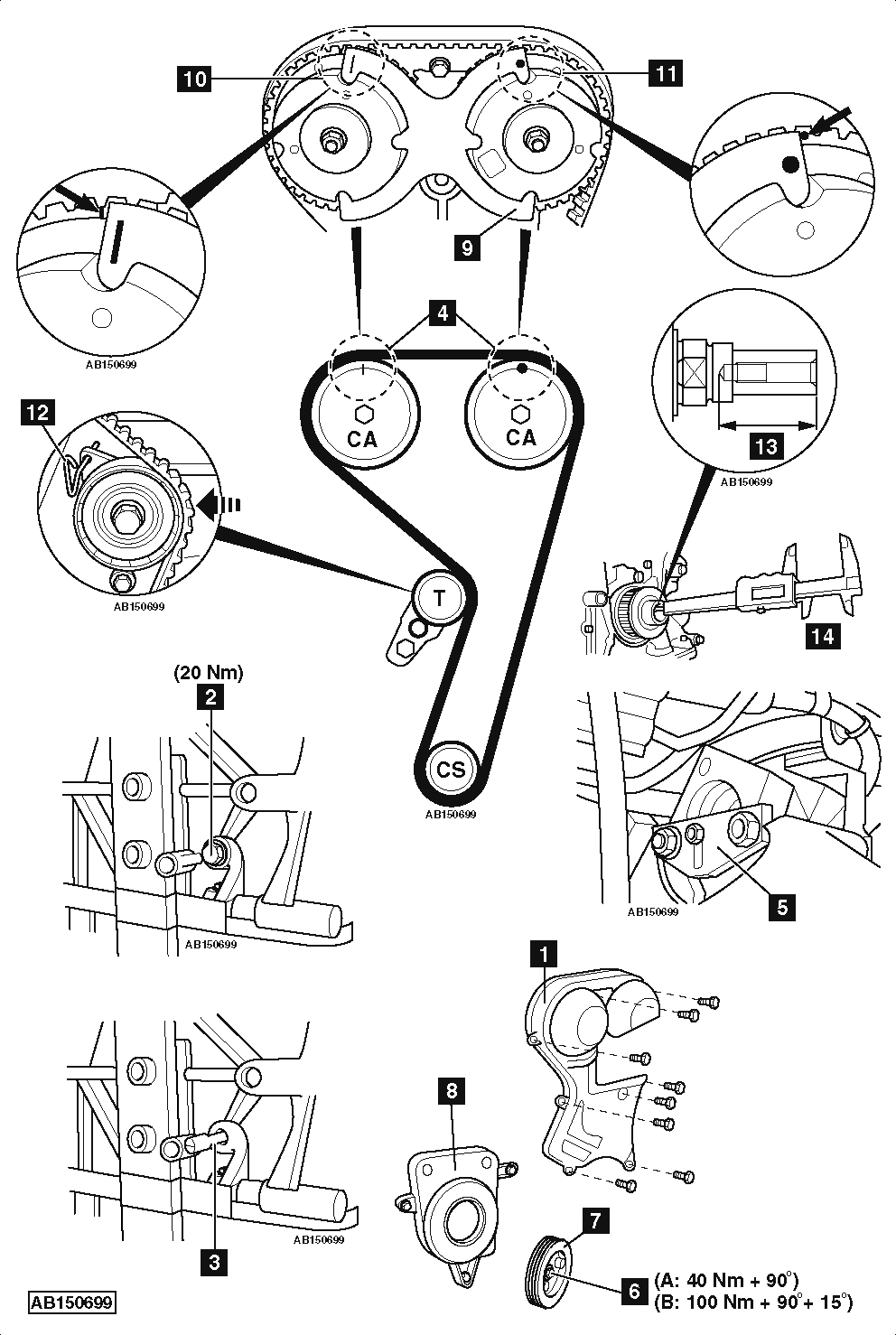
- Timing belt upper cover [1] .
- Blanking plug from cylinder block [2] .
- Turn crankshaft clockwise until just before TDC on No.1 cylinder.
- Fit crankshaft timing pin [3] . Tool No.303-748.
- Turn crankshaft slowly clockwise until it stops against timing pin [3] .
- Ensure timing marks on camshaft sprockets at 12 o’clock position [4] .
- Lock flywheel. Use tool Nos.303-393/303-393-02 [5] .
- Remove:
- Crankshaft pulley bolt [6] .
- Crankshaft pulley [7] .
- Timing belt lower cover [8] .
- Support engine.
- Remove:
- RH engine mounting.
- RH engine mounting bracket.
- Fit locking tool to camshaft sprockets [9] . Tool No.303-1097.
- Ensure timing marks on camshaft sprockets aligned with outer edges of locking tool [10] & [11] .
NOTE: Exhaust camshaft sprocket has a scribed timing mark and inlet camshaft sprocket has a dot timing mark.
- Pull on belt to depress tensioner pulley and insert locking pin [12] . Tool No.303-1054.
- Remove timing belt.
Installation
WARNING: Crankshaft sprocket NOT keyed to crankshaft.
NOTE: DO NOT refit used belt.
- Ensure locking tool fitted correctly to camshaft sprockets [9] .
- Ensure timing marks on camshaft sprockets aligned with outer edges of locking tool [10] & [11] .
NOTE: Exhaust camshaft sprocket has a scribed timing mark and inlet camshaft sprocket has a dot timing mark.
- Ensure crankshaft at TDC on No.1 cylinder.
- Ensure crankshaft timing pin located correctly [3] .
- Ensure flywheel locked with tool [5] .
- Fit timing belt in clockwise direction, starting at exhaust camshaft sprocket.
- Ensure belt is taut between sprockets.
- Remove tensioner pulley locking pin [12] .
- Check depth of crankshaft threaded hole [13] . Use suitable measuring tool [14] .
- 42 mm: Use new crankshaft pulley bolt (M12 x 29 mm).
- 52 mm: Use new crankshaft pulley bolt (M12 x 44,5 mm).
- Install:
- Timing belt lower cover [8] .
- Crankshaft pulley [7] .
- Crankshaft pulley bolt [6] .
- Tighten crankshaft pulley bolt [6] . Use new bolt. Tightening torque:
- A – M12: 40 Nm + 90°.
- B – M14: 100 Nm + 90°. Wait 10 secs. Tighten crankshaft pulley bolt a further 15°.
- Remove:
- Camshaft sprocket locking tool [9] .
- Crankshaft timing pin [3] .
- Flywheel locking tool [5] .
- Turn crankshaft slowly two turns clockwise until just before TDC on No.1 cylinder.
- Fit crankshaft timing pin [3] .
- Turn crankshaft slowly clockwise until it stops against timing pin [3] .
- Ensure timing marks on camshaft sprockets at 12 o’clock position [4] .
- Fit locking tool to camshaft sprockets [9] .
- Ensure timing marks on camshaft sprockets aligned with outer edges of locking tool [10] & [11] .
NOTE: Exhaust camshaft sprocket has a scribed timing mark and inlet camshaft sprocket has a dot timing mark.
- If not: Repeat installation and tensioning procedures.
- Remove:
- Crankshaft timing pin [3] .
- Camshaft sprocket locking tool [9] .
- Fit blanking plug and tighten to 20 Nm [2] .
- Install components in reverse order of removal.
NOTE: Special tools required for fitting new auxiliary drive belt(s).