Replacement Interval Guide
- Audi recommend replacement every 75,000 miles or 5 years (tensioner pulley must also be replaced).
- The previous use and service history of the vehicle must always be taken into account.
Check For Engine Damage
CAUTION: This engine has been identified as an INTERFERENCE engine in which the possibility of valve-to-piston damage in the event of a timing belt failure is MOST LIKELY to occur. A compression check of all cylinders should be performed before removing the cylinder head(s).
Repair Times – hrs
| Remove & install | 2,20 |
Special Tools
- Auxiliary drive belt tensioner locking pin – Audi No.T10060A.
- Camshaft sprocket holding tool – Audi No.T10172/4.
- Camshaft sprocket locking tool – Audi No.3359.
- Crankshaft sprocket locking tool – Audi No.T10050 or T10100.
- Tensioner pulley locking pin – Audi No.T10265.
- Tensioning tool – Audi No.T10264.
Special Precautions
- Disconnect battery earth lead.
- DO NOT turn crankshaft or camshaft when timing belt removed.
- Remove glow plugs to ease turning engine.
- Turn engine in normal direction of rotation (unless otherwise stated).
- DO NOT turn engine via camshaft or other sprockets.
- Observe all tightening torques.
Removal
- Raise and support front of vehicle.
- Remove:
- Engine top cover.
- RH front wheel.
- Engine undershield.
- RH wheel arch liner.
- Disconnect:
- Fuel supply and return pipes.
- Coolant expansion tank hose.
- Remove:
- Turbocharger inlet hose.
- Throttle body assembly.
- Fuel filter. DO NOT disconnect pipes.
- Fuel filter bracket.
- Windscreen washer reservoir filler neck.
- Coolant expansion tank. DO NOT disconnect hoses.
- Auxiliary drive belt. Use tool No.T10060A.
NOTE: Mark direction of rotation on belt with chalk if belt is to be reused.
- Auxiliary drive belt tensioner.
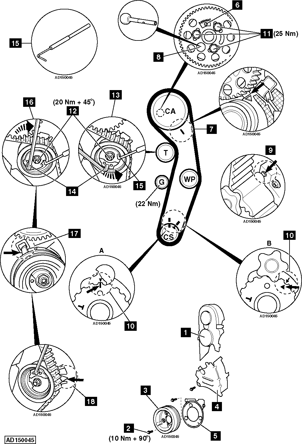
- Timing belt upper cover [1] .
- Turbocharger lower air duct.
- Crankshaft pulley centre cap.
- Crankshaft pulley bolts [2] .
- Crankshaft pulley [3] .
- Timing belt centre cover [4] .
- Timing belt lower cover [5] .
- Turn crankshaft clockwise to TDC on No.1 cylinder.
- Ensure camshaft sprocket window at position as shown [6] .
- Ensure timing mark aligned with notch on camshaft sprocket hub [7] .
NOTE: Notch located behind camshaft sprocket teeth.
- Lock camshaft. Use tool No.3359 [8] .
- Lock crankshaft sprocket:
- Type A: Use tool No.T10050 [A] .
- Type B: Use tool No.T10100 [B] .
NOTE: Ensure lug of crankshaft sprocket locking tool located in oil seal housing [9] .
- Ensure timing marks aligned [10] .
- Slacken camshaft sprocket bolts [11] .
NOTE: Slacken bolts until sprocket can be moved within slotted holes.
- Slacken tensioner pulley nut [12] .
- Turn tensioner pulley anti-clockwise until locking pin can be inserted [13] . Use tool No.T10264 [14] .
- Insert locking pin in tensioner pulley [15] . Tool No.T10265.
- Turn tensioner pulley fully clockwise until it reaches stop [16] . Use tool No.T10264 [14] .
- Lightly tighten tensioner pulley nut [12] .
- Remove timing belt, starting at water pump sprocket.
NOTE: Mark direction of rotation on belt with chalk if belt is to be reused.
Installation
NOTE: Engine must be cold.
- Ensure camshaft locked with tool [8] .
- Ensure crankshaft sprocket locking tool located correctly [A] or [B] .
NOTE: Ensure lug of crankshaft sprocket locking tool located in oil seal housing [9] .
- Ensure timing marks aligned [10] .
- Ensure tensioner pulley locking pin inserted [15] .
- Ensure tensioner pulley retaining lug is properly engaged [17] .
- Turn camshaft sprocket fully clockwise in slotted holes.
NOTE: Sprocket should turn freely without tilting.
- Fit timing belt in following order:
- Camshaft sprocket.
- Tensioner pulley.
- Crankshaft sprocket.
- Water pump sprocket.
NOTE: If reusing old belt, observe direction of rotation marks on belt. Ensure belt is taut between sprockets on non-tensioned side.
- Remove locking pin from tensioner pulley [15] .
- Slacken tensioner pulley nut [12] .
- Turn tensioner pulley slowly clockwise until pointer aligned with notch [18] .
NOTE: Ensure tensioner pulley nut does not turn [12] .
- Hold tensioner pulley. Use tool No.T10264 [14] .
- Tighten tensioner pulley nut [12] . Tightening torque: 20 Nm + 45°.
NOTE: As tensioner pulley nut is tightened, the pointer may move clockwise 5 mm maximum. DO NOT adjust position of tensioner pulley. Timing belt will settle once run in.
- Hold camshaft sprocket. Use tool No.T10172/4.
NOTE: Ensure belt is taut between sprockets on non-tensioned side.
- Tighten camshaft sprocket bolts [11] . Tightening torque: 25 Nm.
- Remove:
- Camshaft sprocket holding tool.
- Camshaft sprocket locking tool [8] .
- Crankshaft sprocket locking tool [A] or [B] .
- Turn crankshaft slowly two turns clockwise until just before TDC on No.1 cylinder.
- Fit camshaft sprocket locking tool while slowly turning crankshaft to TDC [8] .
- Ensure timing mark aligned with notch on camshaft sprocket hub [7] .
NOTE: Notch located behind camshaft sprocket teeth.
- Ensure crankshaft sprocket locking tool can be inserted easily [A] or [B] .
NOTE: Ensure lug of crankshaft sprocket locking tool located in oil seal housing [9] .
- Ensure timing marks aligned [10] .
- Ensure tensioner pulley pointer aligned with notch or 5 mm maximum to the right of notch [18] .
- If crankshaft sprocket locking tool cannot be inserted [A] or [B] :
- Hold camshaft sprocket. Use tool No.T10172/4.
- Slacken camshaft sprocket bolts [11] .
NOTE: Slacken bolts until sprocket can be moved within slotted holes.
- Turn crankshaft anti-clockwise until lug of locking tool just passes hole in oil seal housing [9] .
- Turn crankshaft clockwise until lug and hole aligned [9] .
- Lock crankshaft sprocket [A] or [B] .
NOTE: Ensure lug of crankshaft sprocket locking tool located in oil seal housing [9] .
- Ensure timing marks aligned [10] .
- Hold camshaft sprocket. Use tool No.T10172/4.
NOTE: Ensure belt is taut between sprockets on non-tensioned side.
- Tighten camshaft sprocket bolts [11] . Tightening torque: 25 Nm.
- Remove camshaft sprocket locking tool [8] .
- Remove crankshaft sprocket locking tool [A] or [B] .
- Turn crankshaft slowly two turns clockwise until just before TDC on No.1 cylinder.
- Fit camshaft sprocket locking tool while slowly turning crankshaft to TDC [8] .
- Ensure crankshaft sprocket locking tool can be inserted easily [A] or [B] .
NOTE: Ensure lug of crankshaft sprocket locking tool located in oil seal housing [9] .
- Ensure timing marks aligned [10] .
- Ensure tensioner pulley pointer aligned with notch or 5 mm maximum to the right of notch [18] .
- Remove camshaft sprocket locking tool [8] .
- Remove crankshaft sprocket locking tool [A] or [B] .
- Install components in reverse order of removal.
- Tighten crankshaft pulley bolts [2] . Tightening torque: 10 Nm + 90°. Use new bolts.