Replacement Interval Guide
- Audi recommend replacement every 75,000 miles or 5 years.
- The previous use and service history of the vehicle must always be taken into account.
Check For Engine Damage
CAUTION: This engine has been identified as an INTERFERENCE engine in which the possibility of valve-to-piston damage in the event of a timing belt failure is MOST LIKELY to occur. A compression check of all cylinders should be performed before removing the cylinder head(s).
Repair Times – hrs
| Remove & install: | |
|---|---|
| A1 | 2,70 |
| A3 | 2,20 |
Special Tools
- Camshaft sprocket/high-pressure fuel pump sprocket holding tool – No.T10172/2.
- Camshaft/high-pressure fuel pump locking tool – 2 x No.3359.
- Crankshaft sprocket locking tool – No.T10050.
- Multi-spline socket – No.T10385.
- Tensioner pulley adjusting tool – No.T10264 or T10409.
- Tensioner pulley locking tool – No.T10265.
Special Precautions
- Disconnect battery earth lead.
- DO NOT turn crankshaft or camshaft when timing belt removed.
- Remove glow plugs to ease turning engine.
- Turn engine in normal direction of rotation (unless otherwise stated).
- DO NOT turn engine via camshaft or other sprockets.
- Observe all tightening torques.
Removal
- Raise and support front of vehicle.
- Remove engine top cover.
- Disconnect diesel particulate filter (DPF) pressure sensor multi-plug.
- Remove diesel particulate filter (DPF) pressure sensor bracket.
- Disconnect:
- Fuel supply and return pipes.
- Fuel pre-heater valve.
- Remove fuel filter. DO NOT disconnect hoses.
- Disconnect coolant level sensor multi-plug.
- A1: Move coolant expansion tank to one side. DO NOT disconnect hoses.
- Disconnect engine coolant temperature (ECT) sensor multi-plug.
- Detach coolant pipe support bracket from engine mounting bracket. DO NOT disconnect hoses.
- Remove timing belt upper cover [1] .
- Remove:
- RH front wheel.
- RH wheel arch liner.
- Engine undershield.
- Auxiliary drive belt.
- Crankshaft pulley bolts [2] .
- Crankshaft pulley [3] .
- A1: Support engine.
- Remove:
- Timing belt lower cover [4] .
- A1: RH engine mounting.
- A1: RH engine mounting bracket.
- Turn crankshaft clockwise to TDC on No.1 cylinder.
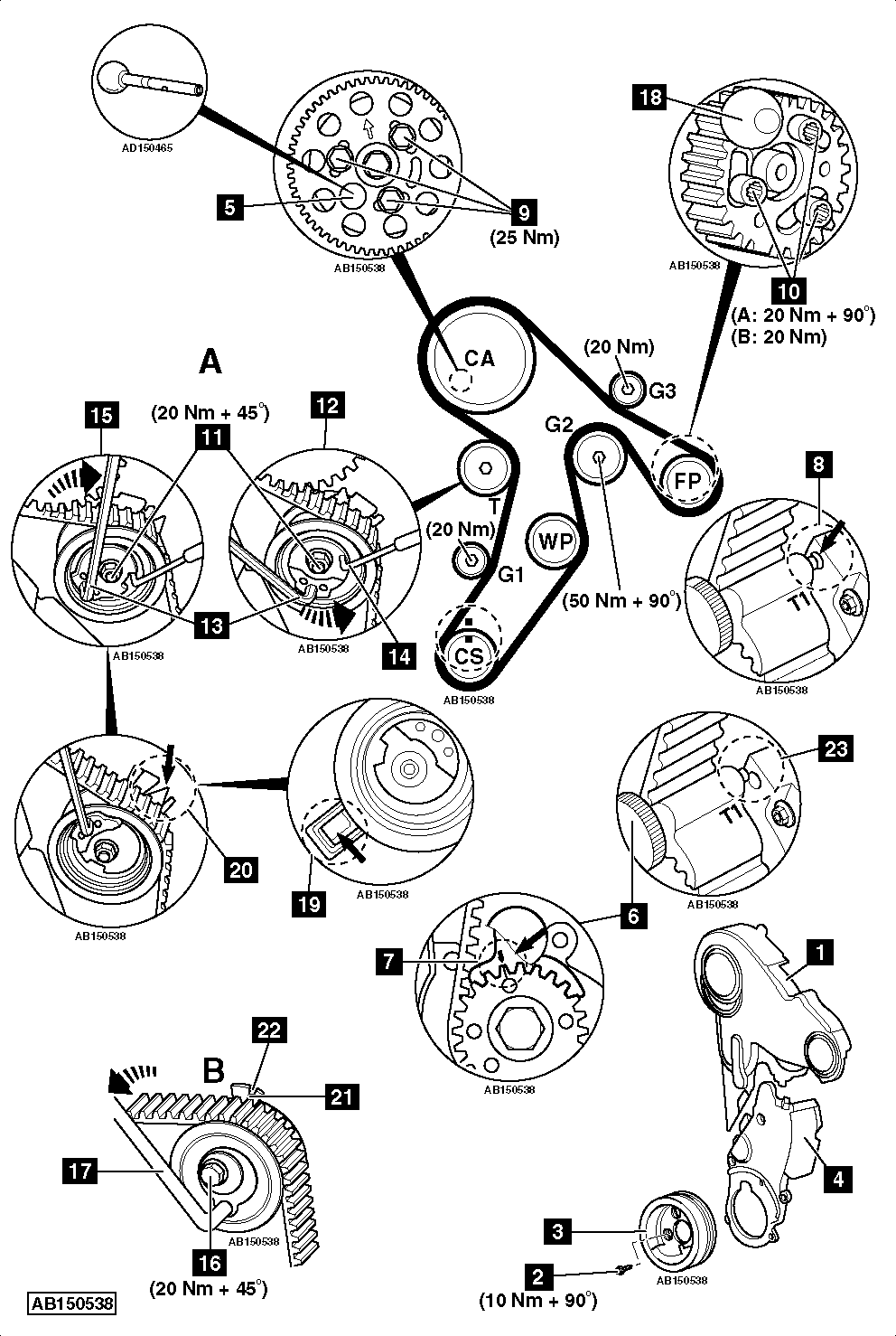
- Lock camshaft [5] . Use tool No.3359.
- Lock crankshaft sprocket [6] . Use tool No.T10050.
- Ensure timing marks aligned [7] .
- Ensure lug of crankshaft sprocket locking tool located in oil seal housing [8] .
- Slacken camshaft sprocket bolts [9] .
- Slacken high-pressure fuel pump sprocket bolts [10] . Use tool No.T10385.
NOTE: There are two types of tensioner pulley.
- Tensioner pulley type A:
- Slacken tensioner pulley nut [11] .
- Turn tensioner pulley anti-clockwise until locking tool can be inserted [12] . Use tool No.T10264 [13] .
- Insert locking tool in tensioner pulley [14] . Tool No.T10265.
- Turn tensioner pulley fully clockwise until it reaches stop [15] . Use tool No.T10264 [13] .
- Tighten tensioner pulley nut finger tight [11] .
- Tensioner pulley type B:
- Slacken tensioner pulley nut [16] .
- Turn tensioner pulley clockwise to release tension on belt. Use tool No.T10409 [17] .
- Tighten tensioner pulley nut finger tight [16] .
- Remove timing belt, starting at guide pulley (G3).
NOTE: Mark direction of rotation on belt with chalk if belt is to be reused.
Installation
NOTE: Engine must be COLD.
- Ensure camshaft locked with tool [5] .
- Tighten camshaft sprocket bolts finger tight [9] .
- Fit new high-pressure fuel pump sprocket bolts [10] . Tighten bolts finger tight.
NOTE: Sprockets should turn freely but not tilt.
- Ensure crankshaft sprocket locking tool located correctly [6] & [8] .
- Lock high-pressure fuel pump [18] . Use tool No.3359.
- Turn camshaft sprocket fully clockwise in slotted holes.
- Turn high-pressure fuel pump sprocket fully clockwise in slotted holes.
- Fit timing belt in following order:
- Crankshaft sprocket.
- Guide pulley (G1).
- Tensioner pulley.
- Camshaft sprocket.
- Water pump sprocket.
- Guide pulley (G3).
- High-pressure fuel pump sprocket.
- Guide pulley (G2).
- Turn camshaft sprocket anti-clockwise to remove slack from belt between camshaft sprocket and high-pressure fuel pump sprocket. Use tool No.T10172/2.
- Hold camshaft sprocket.
- Tighten camshaft sprocket and high-pressure fuel pump sprocket bolts [9] & [10] . Tightening torque: 20 Nm.
- Tensioner pulley type A:
- Slacken tensioner pulley nut [11] .
- Remove locking tool from tensioner pulley [14] .
- Ensure tensioner pulley retaining lug is properly engaged [19] .
- Turn tensioner pulley slowly clockwise until pointer aligned with notch [20] .
NOTE: Ensure tensioner pulley nut does not turn [11] .
- Hold tensioner pulley. Use tool No.T10264 [13] .
- Tighten tensioner pulley nut [11] . Tightening torque: 20 Nm + 45°.
- Tensioner pulley type B:
- Slacken tensioner pulley nut [16] .
- Turn tensioner pulley anti-clockwise until pointer aligned with notch [21] & [22] . Use tool No.T10409 [17] .
NOTE: Ensure tensioner pulley nut does not turn [16] .
- Hold tensioner pulley. Use tool No.T10409 [17] .
- Tighten tensioner pulley nut [16] . Tightening torque: 20 Nm + 45°.
- Remove:
- Camshaft locking tool [5] .
- High-pressure fuel pump locking tool [18] .
- Crankshaft sprocket locking tool [6] .
- Turn crankshaft slowly two turns clockwise until just before TDC on No.1 cylinder.
- Fit crankshaft sprocket locking tool while slowly turning crankshaft to TDC [6] .
- Ensure lug of crankshaft sprocket locking tool located in oil seal housing [8] .
- Ensure timing marks aligned [7] .
- Ensure camshaft locking tool can be inserted easily [5] .
NOTE: DO NOT insert high-pressure fuel pump locking tool as alignment hole may be slightly misaligned. No adjustment required.
- Ensure tensioner pulley pointer aligned with notch or 5 mm maximum to the left or right of notch [20] or [22] . If not: Repeat tensioning procedure.
- If camshaft locking tool cannot be inserted easily [5] :
- Remove lug of crankshaft sprocket locking tool from hole in oil seal housing.
- Turn crankshaft anti-clockwise until lug of locking tool just passes hole in oil seal housing [23] .
- Turn crankshaft clockwise until camshaft locking tool can be inserted [5] .
- Slacken camshaft sprocket bolts [9] .
NOTE: Lug of crankshaft sprocket locking tool will be positioned to the left or right of hole in oil seal housing.
- If lug of crankshaft sprocket locking tool is positioned to the left of hole in oil seal housing:
- Turn crankshaft clockwise until lug and hole aligned [8] .
- Lock crankshaft sprocket [6] .
- Ensure timing marks aligned [7] .
- Tighten camshaft sprocket bolts [9] . Tightening torque: 20 Nm.
- If lug of crankshaft sprocket locking tool is positioned to the right of hole in oil seal housing:
- Turn crankshaft anti-clockwise until lug of locking tool just passes hole in oil seal housing [23] .
- Turn crankshaft clockwise until lug and hole aligned [8] .
- Lock crankshaft sprocket [6] .
- Ensure timing marks aligned [7] .
- Tighten camshaft sprocket bolts [9] . Tightening torque: 20 Nm.
- Remove locking tools [5] & [6] .
- Turn crankshaft slowly two turns clockwise until just before TDC on No.1 cylinder.
- Lock crankshaft sprocket [6] .
- Ensure timing marks aligned [7] .
- Ensure lug of crankshaft sprocket locking tool located in oil seal housing [8] .
- Ensure camshaft locking tool can be inserted easily [5] .
- Hold camshaft sprocket. Use tool No.T10172/2.
- Tighten camshaft sprocket bolts [5] . Tightening torque: 25 Nm.
- Hold high-pressure fuel pump sprocket. Use tool No.T10172/2.
- Tighten high-pressure fuel pump sprocket bolts [10] . Tightening torque:
- A – A1: 20 Nm + 90°.
- B – A3: 20 Nm.
- Remove locking tools [5] & [6] .
- Install components in reverse order of removal.
- Tighten crankshaft pulley bolts [2] . Tightening torque: 10 Nm + 90°. Use new bolts.