Citroen Dispatch 2.0D HDi 2011-14 cambelt change instructions and replacement inteval. Full guide!
Special tools
- Auxiliary drive belt tensioner tool – Citroën Nos.(-).0188.Z/Q1.
- Hybrid: Auxiliary drive belt tensioner tools – Citroën Nos.(-).1603-E/1603-F.
- Hybrid: Auxiliary drive belt tension gauge – Citroën No.(-).0107.
- Camshaft sprocket locking tool – Citroën No.(-).0188.M.
- C4 Picasso/Grand Picasso: Crankshaft reluctor puller – Citroën No.(-).0188.P.
- Crankshaft sprocket centralizing tool – Citroën No.(-).0188.AH.
- Flywheel timing pin – Citroën No.(-).0188.Y.
- Flywheel locking tool – Citroën No.(-).0188.F.
- Set of blanking plugs – Citroën No.(-).1617-J.
- Timing belt clamp – Citroën No.(-).0188.AD.
Special precautions
- Disconnect battery earth lead.
- DO NOT turn crankshaft or camshaft when timing belt removed.
- Remove spark plugs to ease turning engine.
- Turn engine in normal direction of rotation (unless otherwise stated).
- DO NOT turn engine via camshaft or other sprockets.
- Observe all tightening torques.
Repair times – hrs
| Camshaft drive belt/chain – R & I | 2,60 |
Valve timing procedures

Removal
- Raise and support front of vehicle.
- Remove:
- Engine top cover.
- Engine undershield.
- Turbocharger lower air duct.
- RH front wheel.
- RH splash guard.
- Auxiliary drive belt. Use tool Nos.(-).0188.Z/Q1 or 1603-E/1603-F.
- C4 II/DS4/C4 Picasso/Grand Picasso/DS5/C8: Wiper arms.
- C4 II/DS4/C4 Picasso/Grand Picasso/DS5/C8: Scuttle panel.
- C8/Dispatch/Jumpy: Coolant expansion tank. DO NOT disconnect hoses.
- C4 Picasso/Grand Picasso: Brake fluid reservoir. DO NOT disconnect hoses.
- C4 II/DS4/C4 Picasso/Grand Picasso/DS5/C8: Scuttle panel support.
- C4 II/DS4/C4 Picasso/Grand Picasso/DS5/C8: Sound insulating pad.
- C4 II/DS4/C4 Picasso/Grand Picasso/DS5: Engine bay fuse box cover.
- Disconnect and seal off fuel pipes. Use tool No.(-).1617-J.
- Reposition priming pump.
- Remove priming pump mounting bracket.
- C8/Dispatch/Jumpy: Disconnect exhaust downpipe to centre section.
- Support engine.
- Remove RH engine mounting.
- Move aside engine wiring harness (on timing belt cover).
- Remove:
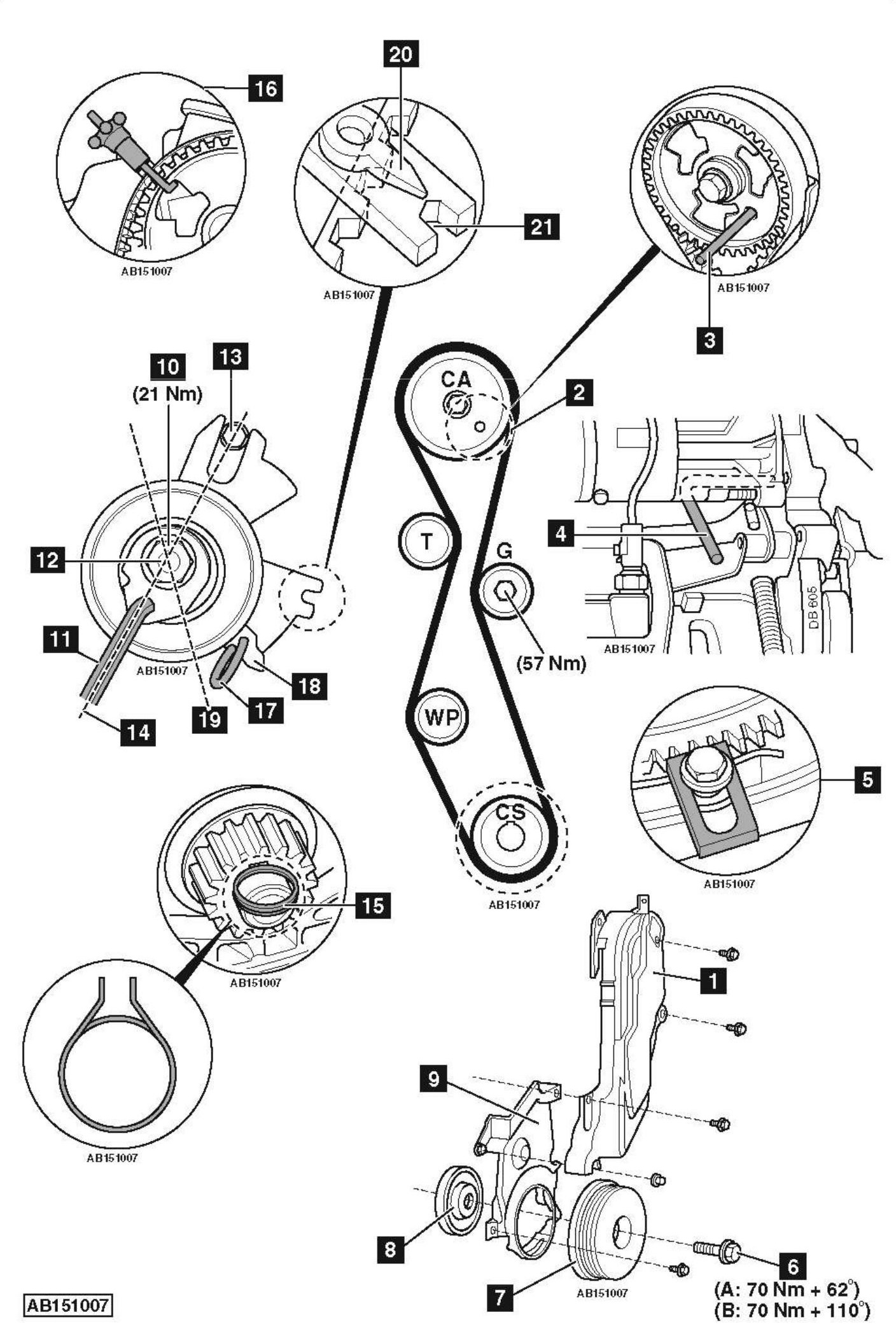
- Timing belt upper cover [1] .
- Crankshaft pulley centre cap.
- Turn crankshaft clockwise to setting position. Ensure camshaft sprocket timing hole at 4 o’clock position [2] .
- Insert:
- Camshaft sprocket locking tool [3] . Tool No.(-).0188.M.
- Flywheel timing pin [4] . Tool No.(-).0188.Y.
- Fit flywheel locking tool [5] . Tool No.(-).0188.F.
- Remove:
- Crankshaft pulley bolt [6] .
NOTE: DO NOT use an impact wrench to slacken crankshaft pulley bolt.
- Crankshaft pulley [7] .
- Disconnect crankshaft position (CKP) sensor multi-plug.
- Remove:
- Reluctor [8] . Use tool No.(-).0188.P.
- Timing belt lower cover [9] .
NOTE: Ensure reluctor is not damaged.
- Slacken tensioner pulley nut [10] .
- Turn tensioner pulley away from belt. Use Allen key [11] .
- Remove timing belt.
Installation
NOTE: DO NOT refit used belt.
- Clean crankshaft pulley bolt and crankshaft threads.
- Check guide pulley and water pump sprocket for smooth operation.
- Check crankshaft sprocket has free movement on keyway.
- Ensure flywheel timing pin located correctly [4] .
- Ensure camshaft sprocket locking tool located correctly [3] .
- If fitting new tensioner pulley:
- Remove tensioner pulley nut and stud [10] & [12] .
- Remove tensioner pulley.
- Fit new tensioner pulley.
- Ensure tensioner pulley located correctly on dowel pin [13] .
- Refit tensioner pulley nut and stud [10] & [12] .
- Ensure tensioner pulley at position shown [14] .
- Finger tighten tensioner pulley nut [10] .
- Centralise crankshaft sprocket [15] . Use tool No.(-).0188-AH.
- Secure timing belt to camshaft sprocket with clamp [16] . Use tool No.(-).0188-AD.
- Fit timing belt in clockwise direction.
- Ensure timing belt is taut between sprockets on non-tensioned side.
- Remove tensioner pulley locking pin [17] .
- If reusing tensioner pulley:
- Ensure tensioner pulley located correctly on dowel pin [13] .
- Ensure tensioner pulley at position shown [14] .
- Finger tighten tensioner pulley nut [10] .
- Centralise crankshaft sprocket [15] . Use tool No.(-).0188-AH.
- Secure timing belt to camshaft sprocket with clamp [16] . Use tool No.(-).0188-AD.
- Fit timing belt in clockwise direction.
- Ensure timing belt is taut between sprockets on non-tensioned side.
- Turn tensioner pulley anti-clockwise until pointer [18] at position shown [19] . Use Allen key [11] .
NOTE: Tensioner pulley pointer to left of notch in baseplate. - Tighten tensioner pulley nut [10] . Tightening torque: 21 Nm.
- Remove tools [15] & [16] .
- Install:
- Crankshaft pulley [7] .
- New crankshaft pulley bolt [6] .
- Tighten crankshaft pulley bolt [6] . Tightening torque: 50 Nm.
NOTE: Ensure there are less than 5 minutes between pre-tightening and final tightening of bolt. - Remove tools [3] , [4] & [5] .
- Turn crankshaft six turns clockwise.
- Install:
- Flywheel timing pin [4] .
- Camshaft sprocket locking tool [3] .
- Flywheel locking tool [5] .
- Slacken:
- Crankshaft pulley bolt [6] .
- Tensioner pulley nut [10] .
- Turn tensioner pulley clockwise until pointer aligned with notch [20] & [21] . Use Allen key [11] .
NOTE: If tensioner pulley turned too far: Turn fully anti-clockwise and repeat tensioning procedure. - Tighten tensioner pulley nut [10] . Tightening torque: 21 Nm.
- Remove tools [3] & [4] .
- Remove:
- Crankshaft pulley bolt [6] .
- Crankshaft pulley [7] .
- Install:
- Timing belt lower cover [9] .
- Reluctor [8] .
- Coat crankshaft pulley bolt with suitable thread locking compound.
- Install:
- Crankshaft pulley [7] .
- Crankshaft pulley bolt [6] .
- Tighten crankshaft pulley bolt [6] . Tightening torque:
- A – Except HYbrid4: 70 Nm + 62°.
- B – HYbrid4: 70 Nm + 110°.
NOTE: DO NOT use an impact wrench to tighten crankshaft pulley bolt.
- Remove flywheel locking tool [5] .
- Install components in reverse order of removal.