Special tools
- Camshaft holding/alignment tool – No.T40061.
- Camshaft locking pin x 2 – No.T40060.
- Camshaft sprocket holding tool – No.T40062.
- Crankshaft turning tool 1 – No.T40058.
- Crankshaft turning tool 2 – No.T40049.
- Crankshaft locking pin – No.3242.
- Injection pump/balancer shaft locking pin – No.3359.
- Primary timing chain tensioner locking tool – No.40071.
General precautions
- Disconnect battery earth lead.
- Remove glow plugs to ease turning engine.
- Turn engine in normal direction of rotation (unless otherwise stated).
- Observe tightening torques.
- If fitted: Mark position of crankshaft position (CKP) sensor before removal.
- Do NOT turn crankshaft via camshaft or other sprockets.
- Do NOT turn crankshaft or camshaft with timing chain removed.
Valve timing procedures

- Timing chains located at rear of engine.
- Removal/installation of timing chain requires:
- Gearbox/drive plate removal.
NOTE: All bolts with an angular torque setting MUST be replaced.
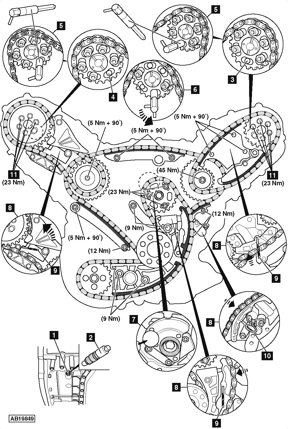
- Turn crankshaft until just before TDC on No.1 cylinder.
- Remove blanking plug from sump [1] .
- Install crankshaft locking pin [2] .
- Slowly turn crankshaft pulley clockwise until locking pin can be inserted in crankshaft [1] . Tighten to 20 Nm.
- Ensure hole in RH camshaft sprocket at 7 o’clock position [3] .
- Ensure hole in LH camshaft sprocket at 5 o’clock position [4] .
- If not, remove crankshaft locking pin and turn crankshaft 1 turn.
- Install camshaft locking pin as shown [5] .
- Rotate camshaft locking pins to alignment position [6] .
NOTE: The side pin of each camshaft locking pin must be in line with centre of camshaft sprocket.
- Ensure balancer shaft can be locked in position [7] .
- Lock timing chain tensioners in retracted position before carrying out engine repairs:
- Push plunger into tensioner housing [8] .
- Insert 3,3 mm pin to lock tensioner plunger [9] .
- Fit primary timing chain tensioner locking tool [10] .
NOTE: If camshaft locking pins cannot be fitted valve timing is incorrect.
- If necessary, slacken bolts of each camshaft sprocket 1 turn [11] .
- Rotate LH camshaft until camshaft locking pin can be fitted [5] .
- Rotate camshaft locking pin to alignment position [6] .
- Repeat procedure for RH camshaft alignment.
- Hold LH camshaft with holding/alignment tool.
- Tighten LH camshaft sprocket bolts [11] . Tightening torque: 5 Nm.
- Remove LH camshaft locking pin [5] .
- Remove camshaft holding/alignment tool.
- Tighten LH camshaft sprocket bolts [11] . Tightening torque: 23 Nm.
- Repeat procedure for RH camshaft alignment.
- Remove crankshaft locking pin [2] .
- Release timing chain tensioner after repairs [9] & [10] .
- Turn crankshaft two turns clockwise until just before TDC on No.1 cylinder.
- Install crankshaft locking pin [2] .
- Slowly turn crankshaft pulley clockwise until locking pin can be inserted in crankshaft [2] .
- Ensure camshaft locking pin can be inserted [5] .
- Rotate camshaft locking pins to alignment position [6] .
NOTE: The side pin of each camshaft locking pin must be in line with centre of camshaft sprocket.