Replacement Interval Guide
- Renault recommend:
- TCe 180: Replacement every 72,000 miles or 6 years (tensioner pulley & guide pulley must be replaced).
- Renaultsport 250: Replacement every 75,000 miles or 6 years (tensioner pulley & guide pulley must be replaced).
- The previous use and service history of the vehicle must always be taken into account.
Check For Engine Damage
CAUTION: This engine has been identified as an INTERFERENCE engine in which the possibility of valve-to-piston damage in the event of a timing belt failure is MOST LIKELY to occur. A compression check of all cylinders should be performed before removing the cylinder head(s).
Repair Times – hrs
| Remove & install | 5,90 |
Special Tools
- Camshaft setting bar – Renault No.Mot.1496.
- Camshaft sprockets locking tool – Renault No.Mot.1801 or Mot.1509-01.
- Crankshaft timing pin – Renault No.Mot.1054.
- Exhaust camshaft blanking plug tool – Renault No.Mot.1488.
- Inlet camshaft blanking plug tool – Renault No.Mot.1487.
Special Precautions
- Disconnect battery earth lead.
- DO NOT turn crankshaft or camshaft when timing belt removed.
- Remove spark plugs to ease turning engine.
- Turn engine in normal direction of rotation (unless otherwise stated).
- DO NOT turn engine via camshaft or other sprockets.
- Observe all tightening torques.
Removal
NOTE: Engines with variable valve timing: Mark camshaft sprockets and camshaft adjusters with chalk or paint prior to timing belt removal to assist alignment on installation.
- Raise and support front of vehicle.
- Remove:
- Engine top cover.
- Engine undershield.
- RH front wheel.
- RH wheel arch liner.
- RH lower support bracket.
- Engine lower tie-bar.
- Auxiliary drive belt.
NOTE: DO NOT refit used belt. Replace auxiliary drive belt tensioner pulley and guide pulley.
- Remove flywheel cover.
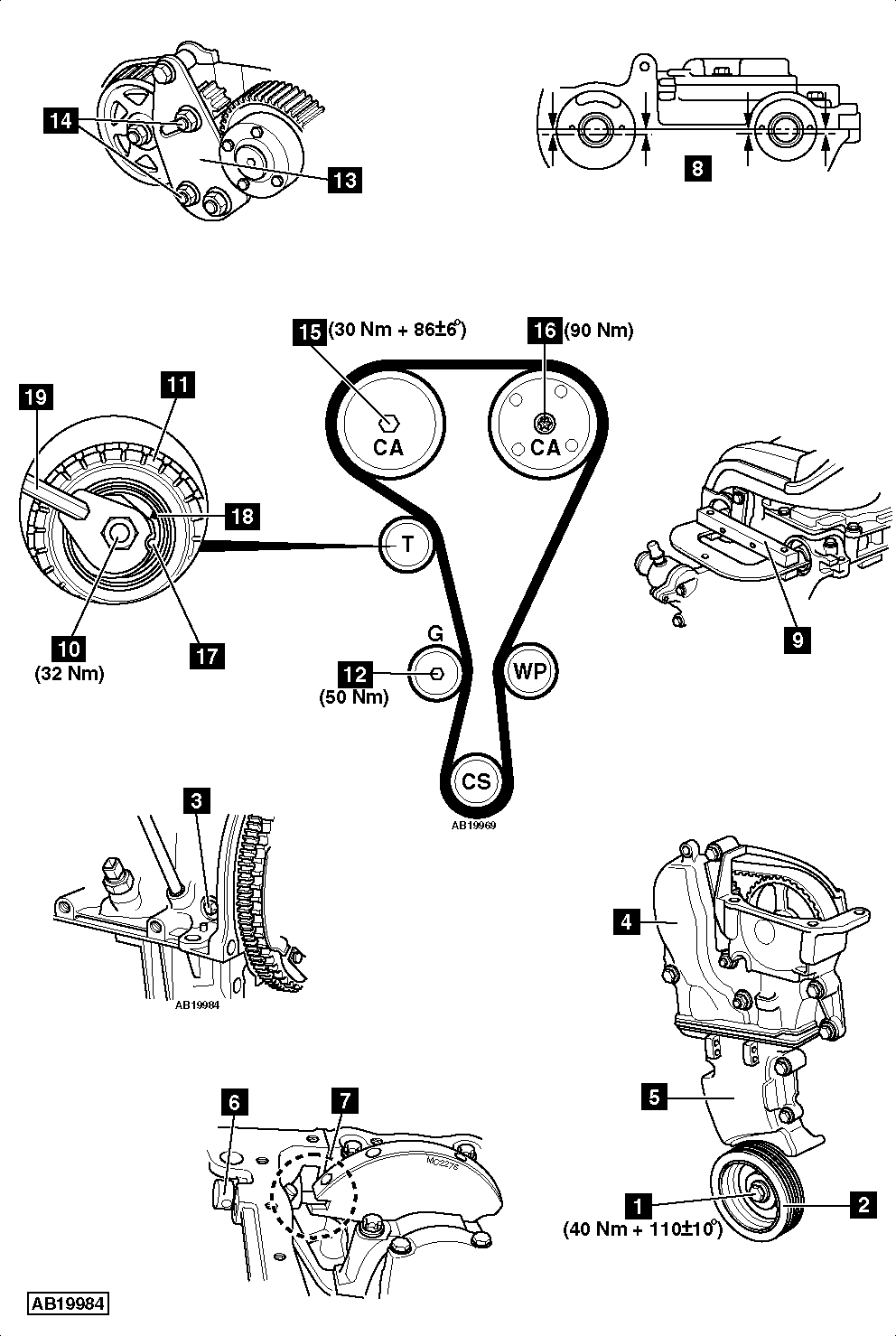
- Lock flywheel with large screwdriver. Slacken crankshaft pulley bolt [1] .
- Remove:
- Crankshaft pulley bolt [1] .
- Crankshaft pulley [2] .
- Water pump. DO NOT disconnect hoses.
- Exhaust downpipe.
- Turbocharger upper air hose.
- RH engine lifting eye.
- Turbocharger (TC) boost pressure vacuum hose.
- Disconnect fuel vapour hose(s) from evaporative emission (EVAP) canister.
- Remove:
- Blanking plug from cylinder block [3] .
- Blanking plugs from rear of camshafts.
- Support engine.
- Remove:
- RH engine mounting and bracket.
- Timing belt upper cover [4] .
- Timing belt lower cover [5] .
- Fit:
- Crankshaft pulley [2] .
- Crankshaft pulley bolt [1] .
- Turn crankshaft clockwise until grooves in rear of camshafts are just before horizontally aligned position.
NOTE: Grooves located below cylinder head upper face.
- Insert crankshaft timing pin in cylinder block [6] . Tool No.Mot.1054.
- Turn crankshaft slightly clockwise. Ensure timing pin located correctly in crankshaft [7] .
- Ensure grooves in rear of camshafts horizontally aligned [8] .
- Fit setting bar to rear of camshafts [9] . Tool No.Mot.1496.
- Remove:
- Crankshaft pulley bolt [1] .
- Crankshaft pulley [2] .
- Slacken tensioner pulley nut [10] .
- Remove:
- Tensioner pulley nut [10] .
- Tensioner pulley [11] .
- Guide pulley bolt [12] .
- Guide pulley.
- Timing belt.
NOTE: Timing belt must always be renewed once it has been removed.
Installation
NOTE: Tensioner pulley and guide pulley MUST be replaced.
- Ensure timing pin located correctly in crankshaft [7] .
NOTE: Ensure timing pin not inserted into crankshaft web balance hole.
- Ensure grooves in rear of camshafts horizontally aligned [8] .
- Ensure setting bar fitted correctly [9] .
- Remove crankshaft sprocket. Degrease sprocket. Degrease end of crankshaft.
- Fit crankshaft sprocket.
- Fit camshaft sprockets locking tool [13] . Tool No.Mot.1801 or Mot.1509-01.
- Tighten camshaft sprockets locking tool nuts [14] . Tightening torque: 80 Nm.
- Remove:
- Blanking plug from inlet camshaft sprocket.
- Exhaust camshaft sprocket nut [15] .
- Inlet camshaft sprocket bolt [16] .
NOTE: Replace camshaft stud if loosened when removing nut.
- Locking tool [13] .
- Camshaft sprockets.
- Degrease ends of camshafts and camshaft sprockets.
- Install camshaft sprockets.
- Finger tighten exhaust camshaft sprocket nut [15] .
- Finger tighten inlet camshaft sprocket bolt [16] .
- Fit new tensioner pulley [11] .
NOTE: Ensure lug on rear of tensioner pulley located in groove in cylinder head.
- Tighten tensioner pulley nut finger tight [10] .
- Fit:
- Timing belt.
- New guide pulley.
- Tighten guide pulley bolt [12] . Tightening torque: 50 Nm.
- Turn tensioner pulley clockwise until marks aligned [17] & [18] . Use 6 mm Allen key [19] .
NOTE: DO NOT turn tensioner pulley anti-clockwise.
- Tighten tensioner pulley nut [10] . Tightening torque: 32 Nm.
- Fit camshaft sprockets locking tool [13] .
- Tighten camshaft sprockets locking tool nuts [14] . Tightening torque: 80 Nm.
- Tighten exhaust camshaft sprocket nut [15] . Tightening torque: 30 Nm.
- Tighten inlet camshaft sprocket bolt [16] . Tightening torque: 30 Nm.
- Remove:
- Camshaft sprockets locking tool [13] .
- Crankshaft timing pin [6] .
- Camshaft setting bar [9] .
- Fit:
- Crankshaft pulley [2] .
- Crankshaft pulley bolt [1] .
- Turn crankshaft two turns clockwise until grooves in rear of camshafts are just before horizontally aligned position.
- Insert crankshaft timing pin in cylinder block [6] .
- Turn crankshaft slightly clockwise. Ensure timing pin located correctly in crankshaft [7] .
NOTE: Ensure timing pin not inserted into crankshaft web balance hole.
- Fit setting bar to rear of camshafts [9] .
- Ensure tensioner pulley marks aligned [17] & [18] . If not: Repeat tensioning procedure.
- Fit camshaft sprockets locking tool [13] .
- Tighten camshaft sprockets locking tool nuts [14] . Tightening torque: 80 Nm.
- Remove exhaust camshaft sprocket nut [15] .
- Remove inlet camshaft sprocket bolt [16] .
- Fit new exhaust camshaft sprocket nut [15] .
- Fit new inlet camshaft sprocket bolt [16] .
- Tighten inlet camshaft sprocket bolt [16] . Tightening torque: 90 Nm.
- Tighten exhaust camshaft sprocket nut [15] . Tightening torque: 30 Nm.
- Remove camshaft setting bar [9] .
- Tighten exhaust camshaft sprocket nut [15] . Tightening torque: 86±6°.
- Remove:
- Crankshaft timing pin [6] .
- Camshaft sprockets locking tool [13] .
- Fit blanking plug [3] .
- Lock flywheel with large screwdriver.
- Fit timing belt lower cover [5] .
- Fit new crankshaft pulley and bolt [1] & [2] .
- Tighten crankshaft bolt [1] . Tightening torque: 40 Nm + 110±10°.
- Fit new blanking plug to inlet camshaft sprocket.
- Fit new blanking plug to rear of inlet camshaft. Use tool No.Mot.1487.
- Fit new blanking plug to rear of exhaust camshaft. Use tool No.Mot.1488.
NOTE: DO NOT start engine without auxiliary drive belt fitted as damage may occur to crankshaft pulley.
- Install components in reverse order of removal.