Citroen C1 1.4 HDi B0 cambelt change instructionts . Full guide!
Replacement Interval Guide
- Citroen recommend:
- 12,500 mile service intervals – replacement every 150,000 miles or 10 years under normal conditions or 120,000 miles or 10 years under adverse conditions.
- 20,000 mile service intervals – replacement every 160,000 miles or 10 years under normal conditions or 112,500 miles or 10 years under adverse conditions.
- The previous use and service history of the vehicle must always be taken into account.
Check For Engine Damage
CAUTION: This engine has been identified as an INTERFERENCE engine in which the possibility of valve-to-piston damage in the event of a timing belt failure is MOST LIKELY to occur. A compression check of all cylinders should be performed before removing the cylinder head.
Repair Times – hrs
| Remove & install: | |
|---|---|
| C1/C2/C3 I/II/C3 Pluriel | 2,70 |
| C3 III | 2,30 |
Special Tools
- Auxiliary drive belt tensioner tool – Citroen No.(-).0194.E/E3.
- Auxiliary drive belt tensioner locking tool – Citroen No.(-).0194.F.
- Camshaft sprocket locking tool – Citroen No.(-).0194.B.
- Crankshaft/high-pressure fuel pump sprocket aligning tool – Citroen No.(-).0194.A.
- Exhaust pipe clamp removal tool – Citroen No.C.193-A.
- Flywheel locking tool – Citroen No.(-).0194.C.
- C3 III: Set of blanking plugs – Citroen No.(-).0194-T.
Special Precautions
- Disconnect battery earth lead.
- DO NOT turn crankshaft or camshaft when timing belt removed.
- Remove glow plugs to ease turning engine.
- Turn engine in normal direction of rotation (unless otherwise stated).
- DO NOT turn engine via camshaft or other sprockets.
- Observe all tightening torques.
Removal
- Raise and support front of vehicle.
- Remove:
- C2/C3: RH front wheel.
- RH inner wing panel.
- C1: RH headlamp.
- C1/C3 III: Auxiliary drive belt. Use tool Nos.(-).0194.E3/F.
- C2/C3 I/II/Pluriel: Auxiliary drive belt. Use tool No.(-).0194.E.
- C1: Remove screws retaining coolant expansion tank. Move coolant expansion tank to one side.
- C3 III: Disconnect and seal off fuel pipes. Use tool No.(-).0194-T.
- Disconnect wiring harness from timing belt upper cover.
- Remove:
- Timing belt upper cover [1] .
- Exhaust downpipe. C1: Use tool No.C.193-A.
- Blanking plug from bell housing.
- Turn crankshaft until flywheel locking tool can be inserted.
- Fit flywheel locking tool. Tool No.(-).0194.C [2] .
- Remove:
- Crankshaft pulley bolt [3] .
- Crankshaft pulley [4] .
- Timing belt lower cover [5] .
- Crankshaft position (CKP) sensor.
- Timing belt guide [6] .
- Flywheel locking tool [2] .
- Support engine.
- Remove RH engine mounting and bracket.
- Fit crankshaft pulley bolt [3] .
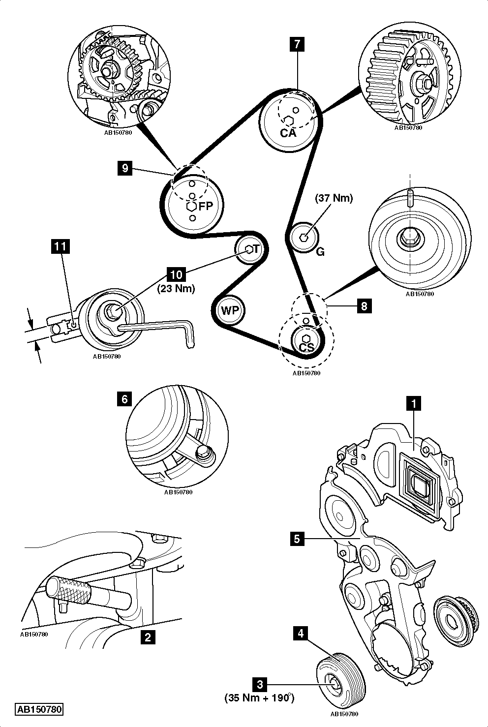
- Turn crankshaft slowly clockwise until camshaft sprocket timing hole aligned [7] .
- Fit camshaft sprocket locking tool. Tool No.(-).0194.B [7] .
- Insert crankshaft aligning tool. Tool No.(-).0194.A [8] .
- Insert high-pressure fuel pump sprocket aligning tool [9] . Tool No.(-).0194.A.
- Slacken tensioner pulley bolt [10] .
- Remove timing belt.NOTE: Ensure crankshaft position (CKP) sensor reluctor is not damaged.
Installation
- Check tensioner pulley, guide pulley and water pump sprocket for smooth operation.
- Ensure camshaft sprocket locking tool located correctly [7] .
- Ensure high-pressure fuel pump sprocket aligning tool located correctly [9] .
- Ensure crankshaft aligning tool located correctly [8] .
- C2/C3 I/II/C3 Pluriel: Fit timing belt in following order:
- Crankshaft sprocket.
- Guide pulley.
- Camshaft sprocket.
- Water pump sprocket.
- High-pressure fuel pump sprocket.
- Tensioner pulley.
- CI/C3 III: Fit timing belt in following order:
- Crankshaft sprocket.
- Guide pulley.
- Camshaft sprocket.
- High-pressure fuel pump sprocket.
- Water pump sprocket.
- Tensioner pulley.
- Turn tensioner pulley anti-clockwise until pointer aligned in window [11] . Use Allen key.
- Tighten tensioner pulley bolt to 23 Nm [10] .
- Remove:
- Camshaft sprocket locking tool [7] .
- Crankshaft aligning tool [8] .
- High-pressure fuel pump sprocket aligning tool [9] .
- C1/C2/C3 I/II/C3 Pluriel: Turn crankshaft slowly ten turns clockwise.
- C3 III: Turn crankshaft slowly six turns clockwise.NOTE: Ensure crankshaft sprocket remains in position.
- Insert:
- Camshaft sprocket locking tool [7] .
- Crankshaft aligning tool [8] .
- High-pressure fuel pump sprocket aligning tool [9] .
- If tools cannot be inserted: Repeat installation procedure.
- Ensure tensioner pulley pointer aligned in window [11] .
- If not: Repeat installation procedure.
- Remove:
- Camshaft sprocket locking tool [7] .
- Crankshaft aligning tool [8] .
- High-pressure fuel pump sprocket aligning tool [9] .
- Fit flywheel locking tool [2] .
- Remove crankshaft pulley bolt [3] .
- Fit:
- Crankshaft position (CKP) sensor.
- Timing belt guide [6] .
- Timing belt lower cover [5] .
- Crankshaft pulley [4] .
- Crankshaft pulley bolt [3] .
- Tighten crankshaft pulley bolt [3] . Tightening torque: 35 Nm + 190°.
- Remove flywheel locking tool [2] .
- Install components in reverse order of removal.