Audi A6 (C6) 2.0 TDI 2005-2008 timing belt replacement instructionts . Full guide for cambelt change!
Replacement Interval Guide
- Audi recommend:
- Replace timing belt every 75,000 miles or 5 years.
- A4 – up to VIN No.8E Z 5 A 400 000: Replace tensioner pulley every 75,000 miles.
- A4 – from VIN No.8E Z 5 A 400 001: Replace tensioner pulley every 150,000 miles.
- A6: Replace tensioner pulley every 150,000 miles.
Check For Engine Damage
CAUTION: This engine has been identified as an INTERFERENCE engine in which the possibility of valve-to-piston damage in the event of a timing belt failure is MOST LIKELY to occur. A compression check of all cylinders should be performed before removing the cylinder head(s).
Repair Times – hrs
| Remove & install: | |
|---|---|
| A4 | 2,60 |
| AT | +0,30 |
| A6 | 3,50 |
Audi Timing Belt Tool
- Auxiliary drive belt tensioner locking pin – Audi No.T10060A.
- Camshaft sprocket holding tool – Audi No.T10172/2.
- Camshaft sprocket locking tools – Audi No.3359.
- Support guides – Audi No.3369.
- Tensioner pulley locking pin – Audi No.T10115.
- Two-pin wrench – Audi No.T10020.
- Type A: Crankshaft sprocket locking tool – Audi No.T10050.
- Type B: Crankshaft sprocket locking tool – Audi No.T10100.
Special Precautions
- Disconnect battery earth lead.
- DO NOT turn crankshaft or camshaft when timing belt removed.
- Remove glow plugs to ease turning engine.
- Turn engine in normal direction of rotation (unless otherwise stated).
- DO NOT turn engine via camshaft or other sprockets.
- Observe all tightening torques.
Removal
- Raise and support front of vehicle.
- Disconnect exhaust pipe for auxiliary heater (if fitted) from engine undershield.
- Remove:
- Front wheels.
- Engine undershield.
- Front bumper cover.
- A6: Headlamps.
- Disconnect:
- Turbocharger/intercooler air hose(s) from bottom of front panel.
- AC pipe from intercooler (if necessary).
- Wiring harness from front panel near cooling fan (if necessary).
- Remove:
- A4: Intercooler air duct.
- Air intake pipe between front panel and air filter.
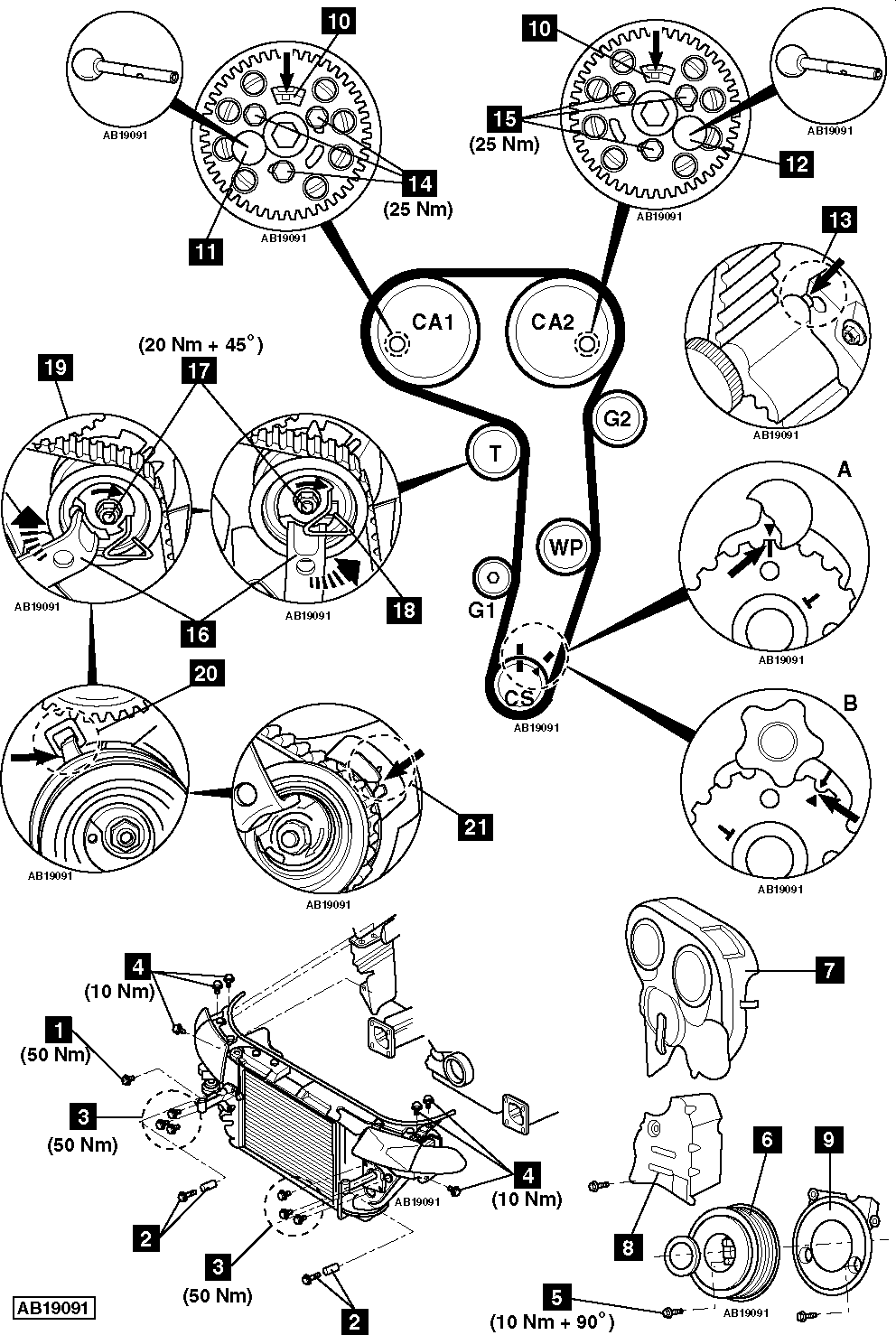
- Front panel bolt (if necessary) [1] .
- Install support guides No.3369 in front panel [2] .
- Remove front panel bolts [3] & [4] .
- Slide front panel forward into service position.
- Refit upper rear bolts in front holes to steady front panel.
- Remove:
- Engine top cover.
- Auxiliary drive belt. Use tool No.T10060A.NOTE: Mark direction of rotation on belt with chalk if belt is to be used.
- Crankshaft pulley centre cap.
- Crankshaft pulley bolts [5] .
- Crankshaft pulley [6] .
- Timing belt upper cover [7] .
- Timing belt centre cover [8] .
- Timing belt lower cover [9] .
- Turn crankshaft clockwise to TDC on No.1 cylinder.
- Ensure window in each camshaft sprocket at 12 o’clock position [10] .
- Lock camshaft sprockets. Use tool Nos.3359 [11] & [12] .
- Lock crankshaft sprocket.NOTE: There are two types of crankshaft sprocket.
- Type A: Use tool No.T10050 [A] .
- Type B: Use tool No.T10100 [B] .
NOTE: Ensure lug of crankshaft sprocket locking tool located in oil seal housing [13] .
- Ensure timing marks aligned [A] or [B] .
- Slacken bolts of each camshaft sprocket [14] & [15] .NOTE: Slacken bolts until sprockets can be moved within slotted holes.
- Hold tensioner pulley. Use tool No.T10020 [16] .
- Slacken tensioner pulley nut [17] .
- Turn tensioner pulley anti-clockwise until locking pin can be inserted. Use tool No.T10020 [16] .
- Insert locking pin in tensioner pulley [18] . Use tool No.T10115.
- Turn tensioner pulley fully clockwise until it reaches stop [19] . Use tool No.T10020.
- Lightly tighten tensioner pulley nut [17] .
- Remove timing belt, starting at water pump sprocket.NOTE: Mark direction of rotation on belt with chalk if belt is to be reused.
Installation
NOTE: Engine must be COLD.
- Ensure camshaft sprockets locked with tools [11] & [12] .
- Ensure crankshaft sprocket locking tool located correctly.
- Ensure timing marks aligned [A] or [B] .
- Ensure tensioner pulley locking pin inserted [18] . Tool No.T10115.
- Ensure tensioner retaining lug is properly engaged [20] .
- Turn camshaft sprockets fully clockwise in slotted holes.NOTE: Sprockets should turn freely without tilting.
- Fit timing belt in clockwise direction, starting at crankshaft sprocket.NOTE: If reusing old belt, observe direction of rotation marks on belt. Ensure belt is taut between sprockets on non-tensioned side.
- Remove locking pin from tensioner pulley [18] .
- Slacken tensioner pulley nut [17] .
- Turn tensioner pulley slowly clockwise until pointer aligned with notch [21] .NOTE: Ensure tensioner pulley nut does not turn [17] .
- Hold tensioner pulley. Use tool No.T10020 [16] .
- Tighten tensioner pulley nut [17] . Tightening torque: 20 Nm + 45°.NOTE: As tensioner pulley nut is tightened, the pointer may move clockwise 5 mm maximum. DO NOT adjust position of tensioner pulley. Timing belt will settle once run in.
- Hold camshaft sprocket (CA1). Use tool No.T10172/2.NOTE: Ensure belt is taut between sprockets on non-tensioned side.
- Tighten bolts of each camshaft sprocket [14] & [15] . Tightening torque: 25 Nm.
- Remove:
- Camshaft sprocket holding tool.
- Camshaft sprocket locking tools [11] & [12] .
- Crankshaft sprocket locking tool [A] or [B] .
- Check valve timing as follows:
- Turn crankshaft slowly two turns clockwise until just before TDC on No.1 cylinder.
- Fit camshaft sprocket (CA1) locking tool while slowly turning crankshaft to TDC [11] . Tool No.3359.
- Ensure camshaft sprocket (CA2) locking tool can be inserted [12] . Tool No.3359.
- Ensure crankshaft sprocket locking tool can be inserted easily [A] or [B] .
- Ensure timing marks aligned [A] or [B] .
- Ensure tensioner pulley pointer aligned with notch or 5 mm maximum to the right of notch [21] .
- If camshaft sprocket (CA2) locking tool cannot be inserted [12] :
- Slacken camshaft sprocket (CA2) bolts [15] .
- Turn camshaft sprocket (CA2) hub until locking tool can be inserted [12] . Tool No.3359.
- Hold camshaft sprocket (CA2). Use tool No.T10172/2.
- Tighten camshaft sprocket (CA2) bolts [15] . Tightening torque: 25 Nm.
- Remove camshaft sprocket holding tool.
- Remove locking tools [11] , [12] , [A] or [B] .
- Turn crankshaft two turns clockwise to TDC on No.1 cylinder.
- Check valve timing.
- If crankshaft sprocket locking tool cannot be inserted [A] or [B] :
- Slacken bolts of each camshaft sprocket [14] & [15] .
- Turn crankshaft sprocket until locking tool can be inserted [A] or [B] .
- Hold camshaft sprocket (CA1). Use tool No.T10172.
- Tighten bolts of each camshaft sprocket [14] & [15] . Tightening torque: 25 Nm.
- Remove camshaft sprocket holding tool.
- Remove locking tools [11] , [12] & [A] or [B] .
- Turn crankshaft two turns clockwise to TDC on No.1 cylinder.
- Check valve timing.
- Install components in reverse order of removal.
- Check headlamp alignment.
- Tighten crankshaft pulley bolts [5] . Tightening torque: 10 Nm + 90°. Use new bolts.